Mechanical
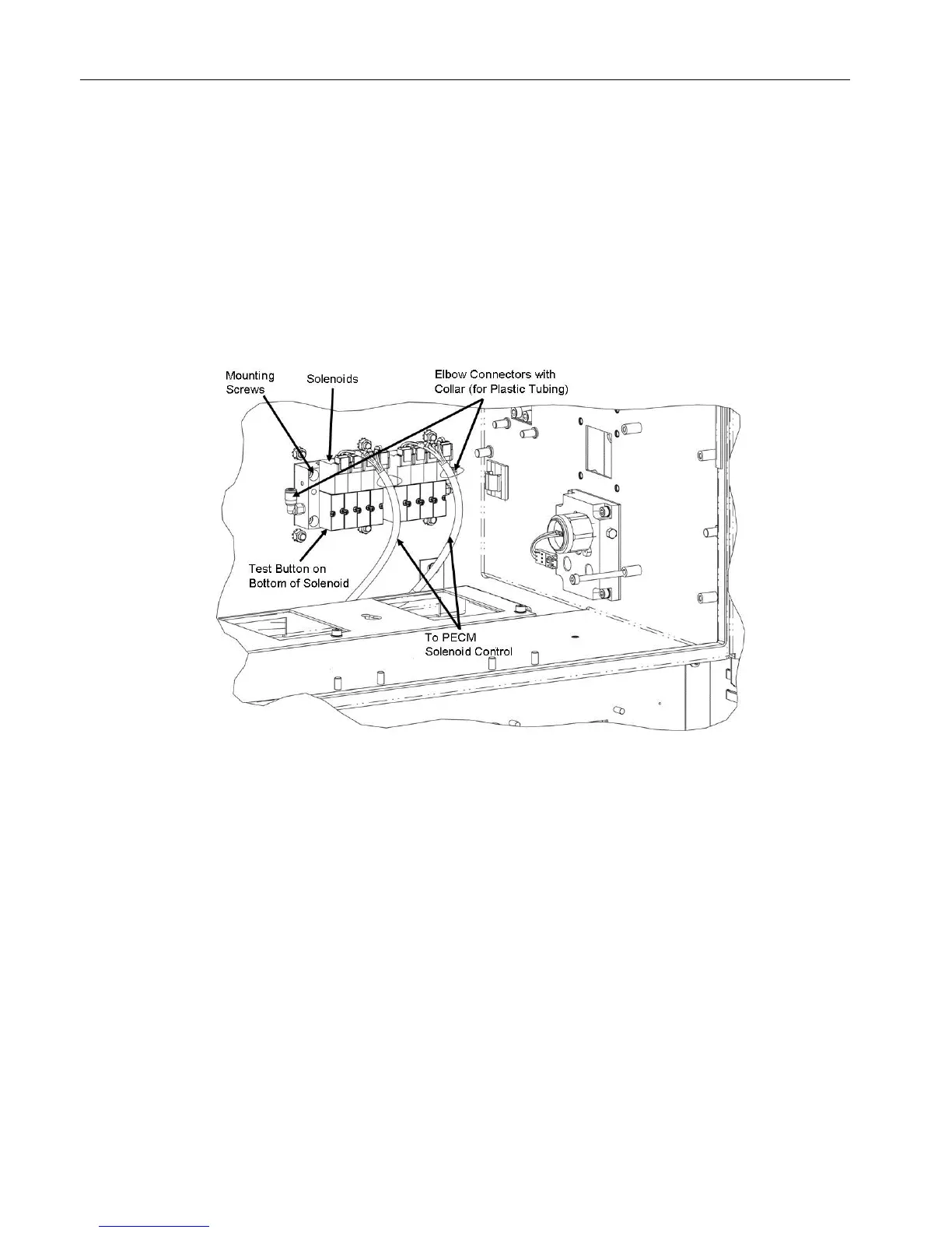
Each SVCM incorporates 8 solenoid valve circuits for driving 3-way and 4-way solenoid valves.
The SVCM is mounted in the Controller Enclosure on the manifold block. It can also be mounted
in a Division 2 purge enclosure. Up to 3 SVCM assemblies can be mounted in the Maxum II.
This allows for up to twelve 3-way solenoids and twelve 4-way solenoids. SVCM-1 is mounted
in the lower right portion of the back wall. SVCM-2 is mounted in the lower left portion of the
back wall. SVCM-3 is mounted (vertically) in the upper right portion of the back wall. The
original SVCM is equipped with Parker solenoids. The newer SVCM is equipped with SMC
solenoids. Manifold in/out SST tubing connections incorporate one touch push type tubing
connectors.
Figure 2-41 Solenoid Control Module
Electronic Compartment Component Descriptions and Maintenance Procedures
2.8 Solenoid Valves
Maxum II Reference Manual
78 Manual, 7/2017, 2000596-001

 Loading...


