Digital Control Channels
On present Maxum II analyzers, the solenoid control circuitry is on the PECM. Digital outputs
assigned to each solenoid valve are shown in the table below. If a digital output is 0 the valve
is OFF; if the output is a 1, the valve is ON. Each group of four valves is identified as being
left or right. There are no digital inputs. See the table below for the numbering pattern of
solenoid valves (same for original and newer versions). Each solenoid valve can be manually
set to the ON or OFF conditions by manually depressing the red button on each solenoid. This
button is on the top-front of each Parker (original) solenoid and on the bottom of each SMC
(new) solenoid.
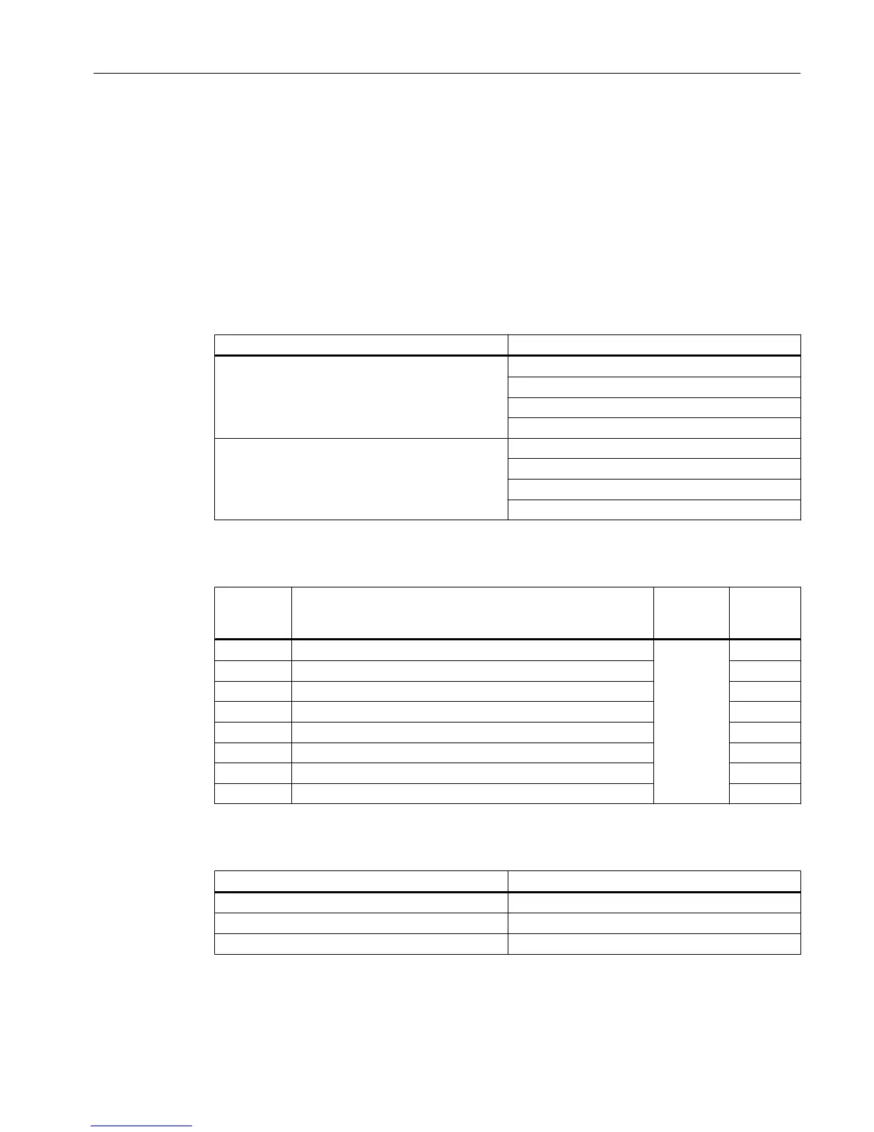
Table 2-5 Digital Output Solenoid Valve Groups
Group Solenoid Valve
Left Valve 1
Valve 2
Valve 3
Valve 4
Right Valve 1
Valve 2
Valve 3
Valve 4
Table 2-6 SVCM I/O Assignments
SYSCON
Channel
Number
I/O Name Group Channel
DO1 LEFT_GROUP_VALVE_1
1
80h
DO 2 LEFT_GROUP_VALVE_2 40h
DO 3 LEFT_GROUP_VALVE_3 20h
DO 4 LEFT_GROUP_VALVE_4 10h
DO 5 RIGHT_GROUP_VALVE_1 08h
DO 6 RIGHT_GROUP_VALVE_2 04h
DO 7 RIGHT_GROUP_VALVE_3 02h
DO 8 RIGHT_GROUP_VALVE_4 01h
Table 2-7 SVCM Fault Indicators
Fault Indicator Fault Condition
VALVE_SWITCH_ERROR Valve status read back is incorrect
J10_DISCONNECTED (left bank connector) J10 connector not connected
J11_DISCONNECTED (right bank connector) J11 connector not connected
Electronic Compartment Component Descriptions and Maintenance Procedures
2.8 Solenoid Valves
Maxum II Reference Manual
Manual, 7/2017, 2000596-001 79

 Loading...


