6 Commissioning Issue 04/04
MICROMASTER 420
22 Compact Operating Manual
P1312 =...
Starting boost (entered in %)
Voltage boost when starting (after an ON command) when using the linear or square-law
V/f characteristic as a % relative to P0305 (rated motor current) or P0350 (stator
resistance). The voltage boost remains active until
1) the setpoint is reached for the first time and
2) the setpoint is reduced to a value that is less than the instantaneous ramp-function
generator output.
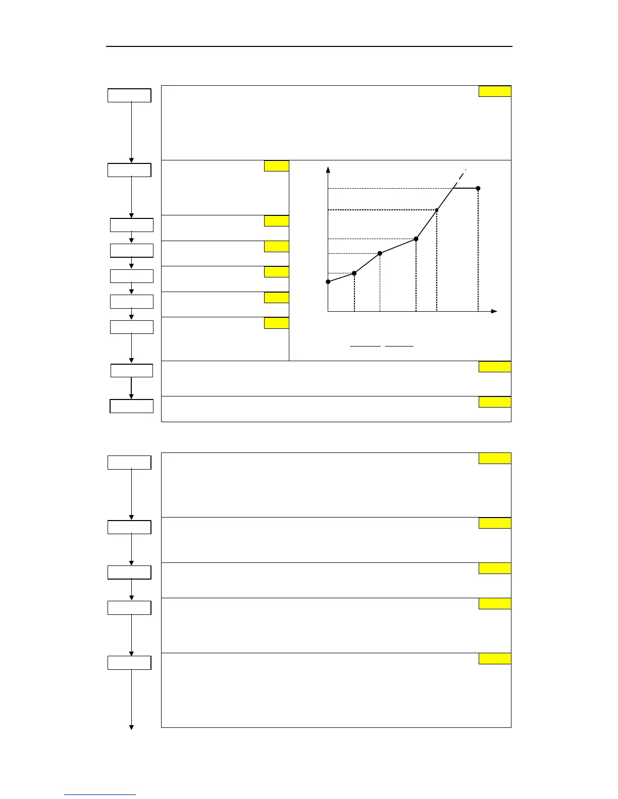
P1320 =...
Programmable V/f freq.
coord. 1
Sets V/f coordinates
(P1320/1321 to P1324/1325) to
define V/f characteristic.
P1321 =...
Programmable. V/f volt.
coord. 1
P1322 =...
Programmable V/f freq.
coord. 2
P1323 =...
Programmable V/f volt.
coord. 2
P1324 =...
Programmable U/f Freq.
Koord. 3
P1325 =...
Programmable V/f volt.
coord. 3
]P0304[V
100[%]
r0395[%]
100[%]
P1310[%]
P1310[V] ⋅⋅=
V
P1325
f1
P1320
f
max
P1082
V
max
r0071
V
n
P0304
P1323
P1321
P1310
f0
0 Hz
f2
P1322
f3
P1324
f
n
P0310
f
V
max
= f(V
dc
, M
max
)
P1335 =...
Slip compensation (entered in %)
Dynamically adjusts output frequency of inverter so that motor speed is kept constant
independent of motor load.
P1338 =...
Resonance damping gain V/f
Defines resonance damping gain for V/f.
6.2.14 Inverter/motor protection
P0290 =...
Inverter overload reaction
Selects reaction of inverter to an internal over-temperature.
0 Reduce output frequency
1 Trip (F0004)
2 Reduce pulse frequency and output frequency
3 Reduce pulse frequency then trip (F0004)
P0292 =...
Inverter temperature warning
Defines the temperature difference (in ºC) between the Overtemperature trip threshold and
the warning threshold of the inverter. The trip threshold is stored internally by the inverter
and cannot be changed by the user.
P0335 =...
Motor cooling (enters the motor cooling system)
0 Self-cooled: Using shaft mounted fan attached to motor
1 Force-cooled: Using separately powered cooling fan
P0610 =...
Motor I
2
t reaction
Defines reaction when motor I
2
t reaches warning threshold.
0 Warning, no reaction, no trip
1 Warning, I
max
reduction, trip F0011
2 Warning, no reaction, trip (F0011)
P0611 =...
Motor I
2
t time constant (entered in s)
The time until the thermal limit of a motor is reached, is calculated via the thermal time
constant. A higher value increases the time at which the motor thermal limit is reached. The
value of P0611 is estimated according to the motor data during quick commissioning or is
calculated using P0340 (Calculating of the motor parameters). When the calculation of
motor parameters during quick commission is complete the stored value can be replaced by
the value given by the motor manufacturer
0.0 %
0.0 %
0.0 Hz
0.0 Hz
0.0 Hz
0.0 Hz
0.0 Hz
0.0 Hz
0
15 °C
0
2
100 s
0.00

 Loading...


