6. TROUBLESHOOTING International English
MICROMASTER 420 Operating Instructions 97
6SE6400-5AA00-0BP0
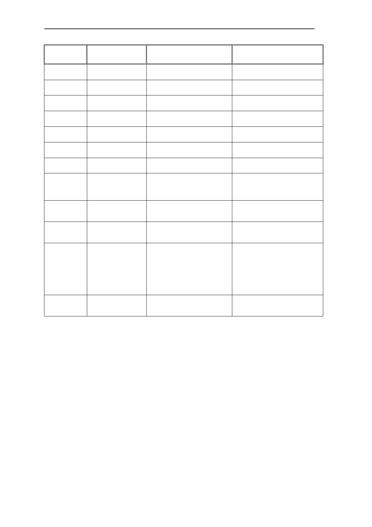
Warning
Code
Description Possible Cause Diagnosis & Remedy
A0706 CB Warning 7 – see
CB manual for details
Communication Board specific See CB User Manual
A0707 CB Warning 8 – see
CB manual for details
Communication Board specific See CB User Manual
A0708 CB Warning 9 – see
CB manual for details
Communication Board specific See CB User Manual
A0709 CB Warning 10 – see
CB manual for details
Communication Board specific See CB User Manual
A0710 CB Communications
Error
Communication with CB
(communication board) is lost.
Check CB Hardware.
A0711 CB Configuration Error CB (communication board) reports
configuration error
Check CB parameters.
A0910 Vdc-max Controller De-
activated.
Vdc-max controller has been de-
activated.
Check parameter inverter input
voltage.
A0911 Vdc-max Controller
active
Ramp-down times are being
extended to prevent overvoltage
trips and to keep the DC link
voltage within acceptable limits
1. Check parameter inverter input
voltage.
2. Check ramp-down times.
A0920 Analogue input
parameters are not set
correctly.
Incorrect parameterization of
analogue input parameters
Analogue input parameters should
not be set to the same value as each
other.
A0921 Analogue Output
Parameters are not set
correctly.
Analogue Output parameters should
not be set to the same value as each
other
A0922 No load applied to
inverter.
Output current lower than
expected.
Low output voltage eg when 0
boost applied at 0Hz
1. Check that load is applied to the
inverter.
2. Check motor parameters
correspond to motor attached.
3. As a result, some functions may
not work correctly, because there is
no normal load condition.
A0923 JOG right and JOG left
signals active
JOG right and JOG left signals
active together
Make sure that JOG right and JOG
left signals are not applied
simultaneously

 Loading...


