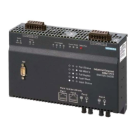
DL1 yellow Diagnostics LED
Blinking if LON is faulty
Blinking if LON is faulty
DL2 red Node in use
LED, normally on LED, normally on
DL3 yellow Service mode
LED normally on LED normally off
DL4 yellow RX LED normally on, off when
receiving data
LED normally off, on when
receiving data
DL5 yellow TX LED normally on, off when
transmitting data
LED normally off, on, off when
transmitting data
LON diagnostics
At the rear of the unit, there are 4 rotary switches for LON addressing (LON physi-
cal address).
Default LON address settings for communication with Guarto MP3
=
1
9
5
D
8
C
4
A
E
B
3
0
F
7
6
2
=
1
9
5
D
8
C
4
A
E
B
3
0
F
7
6
2
=
9
5
D
8
C
4
A
E
B
3
0
F
7
6
2
1
=
1
9
5
D
8
C
4
A
E
B
3
0
F
7
6
2
=
1
9
5
D
8
C
4
A
E
B
3
0
F
7
6
2
=
1
9
5
D
8
C
4
A
E
B
3
0
F
7
6
2
=
9
5
D
8
C
4
A
E
B
3
0
F
7
6
2
1
=
1
9
5
D
8
C
4
A
E
B
3
0
F
7
6
2
CD00251 Rev.A boards CD00251 Rev.B boards
Fig. 14 NK822x LON board rotary switch settings

 Loading...