Structure & function
22
Building Technologies 007798_g_en NK8000 ICC.doc
Fire Safety & Security Products 06.2006
4.1.5 Serial interfaces
NK8223 / NK8225
Although the maximum number of serial lines is 4, they are not always used. There
are two serial lines available on the base module and two on an expansion module.
See the System component list on page 54 for more details about the expan-
sion modules.
NK8222
There are two serial lines available on the base module.
The first serial port can be configured as an RS232 interface using connector
COM1 or as an RS485 interface using connector CN4.
All lines are fully RS232 compliant and have EMC/ESD protection.
No galvanic isolation is provided; all serial lines have a common ground.
4.1.6 LON interface
The processor board has a standard PC/104 interface for system expansion. This
is used for the LON add-on board.
There are two revisions of LON interface boards, which have different LED indica-
tions and different rotary switch settings.
Before checking the LEDs or setting the physical LON address with the rotary
switch, check the revision of the board you are using.
The 8-digit code (CD00251A or CD00251B) can be found on the rear of the inter-
nal board in the upper left corner.
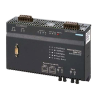
On the top of the NK822x module there are five LED’s and 1 push button, which
indicate the following: (see table following Fig. 13)
Fig. 13 NK822x LON board diagnostic LEDs

 Loading...