HW Installation
27
Building Technologies 007798_g_en NK8000 ICC.doc
Fire Safety & Security Products 06.2006
5.1.2 NK822x hardware installation
Installation
1. Set appropriate I
2
C addresses if I/O modules will be used. Note that:
– Input modules (DF8040) have addresses 1 or 2;
– Output module (DF8020) has address 1;
– Power supply supervision module (DF8090), factory set to address 8.
2. Connect and install I
2
C modules.
3. Connect I/O points to the I/O module.
For more information about the Input/Output modules, including installation
details, see document no. e1762b – CF9000 Input/Output Multiplexing System
Technical Manual.
Note: The names have changed from CF9040 to DF8040, and CF9020 to
DF8020. These changes may not be reflected in earlier documentation.
4. Connect subsystems: (connect one of the following)
– Subsystem lines using the standard RS232 interfaces on COM1 - COM4;
Note: Only COM1 and COM2 available on NK8222.
– The RS485 interface on CN4 (in place of Com1);
– The LON bus on CN3.
5. Connect power supply.
See Fig. 18 p. 28 if using a DF8090 power supply supervision module.
Do not connect or disconnect any device when the device is powered!
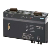
Top view: NK822x connectors
Fig. 16 NK822x electrical interfaces (top view)
Bottom view: NK822x connectors
Fig. 17 Serial RS232-interfaces (bottom view)
LON controls
CN1: Ethernet
CN2: not used
CN3: Power and LON
1 8 5 1 2 1
Note: NK8222 and some NK8223/NK8225
configurations contain no COM3 or COM4.

 Loading...