Product Characteristics
4.5 SCALANCE X101-1POF
4.5.6 SCALANCE X101-1POF Power Supply and Signaling Contact
Power Supply
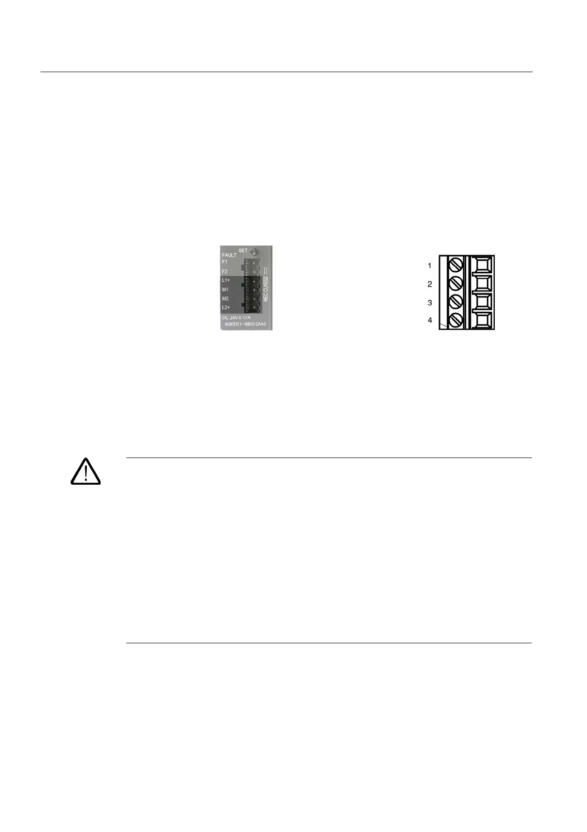
The power supply is connected using a 4-pin plug-in terminal block. The power supply can
be connected redundantly. Both inputs are isolated. There is no distribution of load. When
using a redundant power supply, the power supply unit with the higher output voltage
supplies SCALANCE X101-1POF alone. The power supply is connected over a high
resistance with the enclosure to allow an ungrounded setup.
Figure 4-21 Power supply SCALANCE X101-1POF Figure 4-22 Connector pinout
Pin number Pinout
Pin 1 L1+ (+18 - 32V DC)
Pin 2 M1 (ground)
Pin 1 M2 (ground)
Pin 2 L2+ (+18 - 32V DC)
Warning
The SCALANCE X101-1POF device is designed for operation with safety extra-low voltage.
This means that only safety extra-low voltages (SELV) complying with IEC950/EN60950/
VDE0805 can be connected to the power supply terminals.
The power supply unit to supply SCALANCE X101-1POF must comply with NEC Class 2
(voltage range 18-32 V, current requirement 200 mA).
If the device is connected to a redundant power supply (two separate power supplies), both
must meet these requirements.
The signaling contact can be subjected to a maximum load of 100 mA (safety extra-low
voltage (SELV), DC 24 V).
Never connect SCALANCE X101-1POF to AC voltage.
Never operate SCALANCE X101-1POF with DC voltage higher than 32 V DC.
Industrial Ethernet Media Converters SCALANCE X-100 Series
4-42 Commissioning Manual, 07/2008, A2B00051521A
 Loading...