Table of Contents
Figure 3-5 Stand-By Coupling of two Redundant Rings via Master / Slave Concept of SCALANCE X-400.
Coupling is realized with SCALANCE X101-1 or X101-1LD Media converter
.......................... 3-4
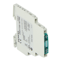
Figure 4-1 SCALANCE X101-1 ................................................................................................................... 4-3
Figure 4-2 RJ-45 connector pinout.............................................................................................................. 4-4
Figure 4-3 Power supply SCALANCE X101-1 ............................................................................................ 4-6
Figure 4-4 Connector pinout........................................................................................................................ 4-6
Figure 4-5 Signaling contact SCALANCE X101-1 ...................................................................................... 4-7
Figure 4-6 Connector pinout........................................................................................................................ 4-7
Figure 4-7 SCALANCE X101-1FL............................................................................................................. 4-15
Figure 4-8 RJ-45 connector pinout............................................................................................................ 4-16
Figure 4-9 Power supply SCALANCE X101-1FL ...................................................................................... 4-18
Figure 4-10 Connector pinout...................................................................................................................... 4-18
Figure 4-11 Signaling contact SCALANCE X101-1FL ................................................................................ 4-19
Figure 4-12 Connector pinout...................................................................................................................... 4-19
Figure 4-13 SCALANCE X101-1LD ............................................................................................................ 4-27
Figure 4-14 RJ-45 connector pinout............................................................................................................ 4-28
Figure 4-15 Power supply SCALANCE X101-1LD...................................................................................... 4-30
Figure 4-16 Connector pinout...................................................................................................................... 4-30
Figure 4-17 Signaling contact SCALANCE X101-1LD............................................................................... 4-31
Figure 4-18 Connector pinout...................................................................................................................... 4-31
Figure 4-19 SCALANCE X101-1POF.......................................................................................................... 4-39
Figure 4-20 RJ-45 connector pinout............................................................................................................ 4-40
Figure 4-21 Power supply SCALANCE X101-1POF................................................................................... 4-42
Figure 4-22 Connector pinout...................................................................................................................... 4-42
Figure 4-23 Signaling contact SCALANCE X101-1POF ............................................................................. 4-43
Figure 4-24 Connector pinout...................................................................................................................... 4-43
Figure 5-1 Installation on a DIN rail (35 mm) .............................................................................................. 5-2
Figure 5-2 Removing from a DIN rail (35 mm) ............................................................................................ 5-3
Figure 5-3 Installation on a SIMATIC S7-300 DIN rail ................................................................................ 5-4
Figure 5-4 IE FC RJ-45 plug 180 ................................................................................................................ 5-6
Figure 5-5 Inserting the IE FC RJ-45 plug 180 ........................................................................................... 5-7
Figure 5-6 Unlatching the RJ-45 plug.......................................................................................................... 5-8
Figure 8-1 Dimension drawing .................................................................................................................... 8-1
Figure 8-2 Dimension drawing / Side view .................................................................................................. 8-2
Figure 8-3 Bending radii .............................................................................................................................. 8-3
Industrial Ethernet Media Converters SCALANCE X-100 Series
Commissioning Manual, 07/2008, A2B00051521A
v
 Loading...