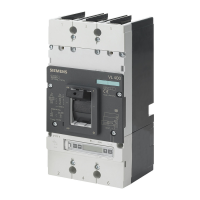
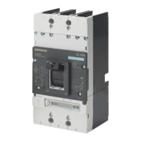
Dimensional drawings
13.8 VL160 (3VL2) and VL250 (3VL3) with RCD module, 3- and 4-pole, to 250 A
3VL molded-case circuit breakers
System Manual, 03/2009, 110 0110 - 02 DS 01
287
( 6 )
( 1 )
( 1 1 )
( 1 )
( 1 1 )
( 1 2 )
( 1 )
( 2 )
( 1 2 )
( 1 0 )
( 1 1 )
( 1 2 )
6 . 5
1 . 0 - 3
2 9
1 0 2 . 5
3 5
5 1
2 7 - ( V L 1 6 0 )
2 9 - ( V L 2 5 0 )
4 0 5 . 5
8 5 . 5
1 4 3
8 7
9 5 . 5
8 0
4 4 . 5
( 4 P )
3 5
3 5 9 . 5
6 1 . 5
1 3 8 . 5
3 5
Æ
1 2 0
3 8 5 ( V L 2 5 0 )
4 4 . 5
3 5 9 . 5
1 2 0
X
Z
( 7 )
1 1 . 1 ( V L 2 5 0 )
Y
3 5
( 4 P )
X
N S E 0 _ 0 1 2 0 1 a
X
7 ( V L 1 6 0 )
Æ
4 4 . 5
Æ
1 1 . 1 ( V L 2 5 0 )
7 ( V L 1 6 0 )
Æ
2 2 ( V L 2 5 0 )
2 0 ( V L 1 6 0 )
3 7 9 ( V L 1 6 0 )
3 8 5 ( V L 2 5 0 )
3 7 9 ( V L 1 6 0 )
Y
1 3 3 ( V L 2 5 0 )
1 3 0 ( V L 1 6 0 )
1 3 3 ( V L 2 5 0 )
1 3 0 ( V L 1 6 0 )
(1) Interphase barrier
(2) Front connecting bars
(3) Terminal covers (standard)
(4) Rear connections (long)
(5) Rear connections (short)
(6) External surface of cabinet door
(7) Mounting level
(8) Rear pad-type terminals (long)
(9) Rear pad-type terminals (short)
(10) Flared busbar extensions
(11) Cover frame for door cutout (for circuit breakers with RCD module)
(12) Cover frame for door cutout (for circuit breakers with toggle handle)

 Loading...


