C-6
C7-613 Control System
A5E00138934-03
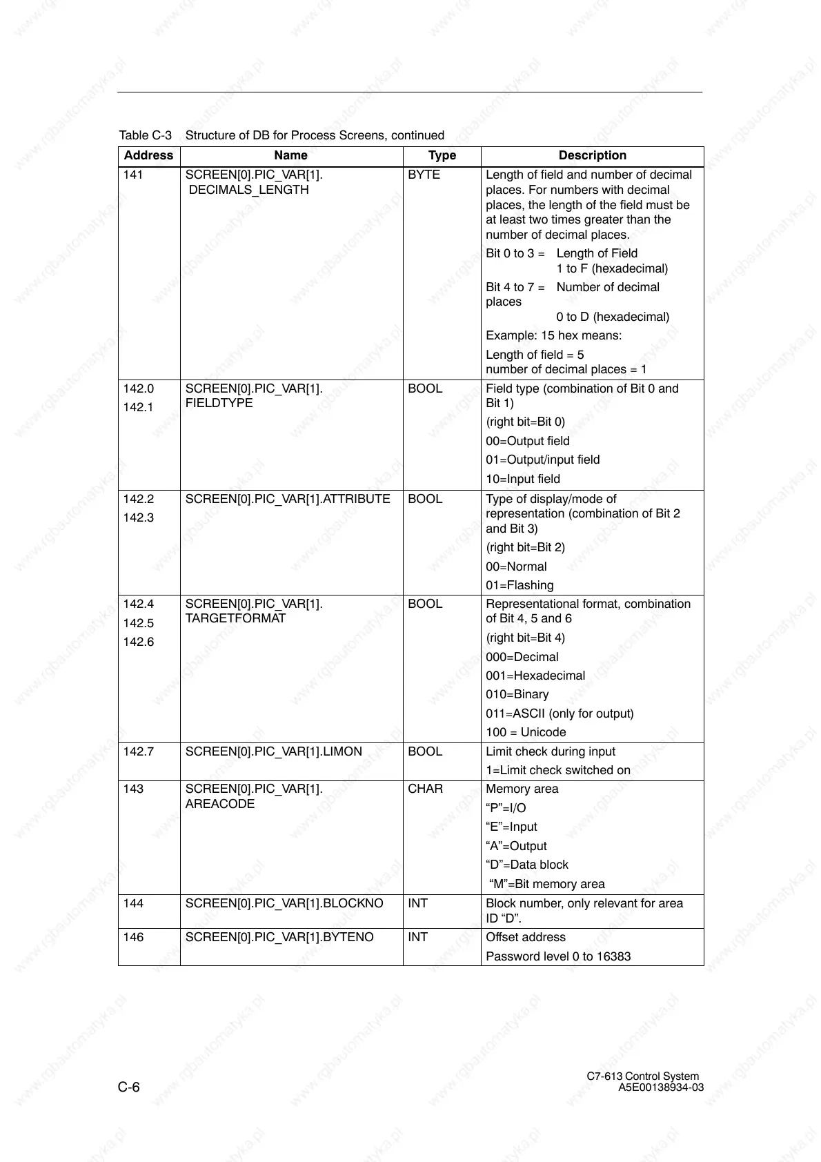
Table C-3 Structure of DB for Process Screens, continued
Address DescriptionTypeName
141 SCREEN[0].PIC_VAR[1].
DECIMALS_LENGTH
BYTE Length of field and number of decimal
places. For numbers with decimal
places, the length of the field must be
at least two times greater than the
number of decimal places.
Bit 0 to 3 = Length of Field
1 to F (hexadecimal)
Bit 4 to 7 = Number of decimal
places
0 to D (hexadecimal)
Example: 15 hex means:
Length of field = 5
number of decimal places = 1
142.0
142.1
SCREEN[0].PIC_VAR[1].
FIELDTYPE
BOOL Field type (combination of Bit 0 and
Bit 1)
(right bit=Bit 0)
00=Output field
01=Output/input field
10=Input field
142.2
142.3
SCREEN[0].PIC_VAR[1].ATTRIBUTE BOOL Type of display/mode of
representation (combination of Bit 2
and Bit 3)
(right bit=Bit 2)
00=Normal
01=Flashing
142.4
142.5
142.6
SCREEN[0].PIC_VAR[1].
TARGETFORMAT
BOOL Representational format, combination
of Bit 4, 5 and 6
(right bit=Bit 4)
000=Decimal
001=Hexadecimal
010=Binary
011=ASCII (only for output)
100 = Unicode
142.7 SCREEN[0].PIC_VAR[1].LIMON BOOL Limit check during input
1=Limit check switched on
143 SCREEN[0].PIC_VAR[1].
AREACODE
CHAR Memory area
“P”=I/O
“E”=Input
“A”=Output
“D”=Data block
“M”=Bit memory area
144 SCREEN[0].PIC_VAR[1].BLOCKNO INT Block number, only relevant for area
ID “D”.
146 SCREEN[0].PIC_VAR[1].BYTENO INT Offset address
Password level 0 to 16383