Technical specifications
6.4 Pinout of the D-sub socket
SIMATIC CC7
Operating Instructions, 10/2019, C79000-G8976-C503-02
129
6.4 Pinout of the D-sub socket
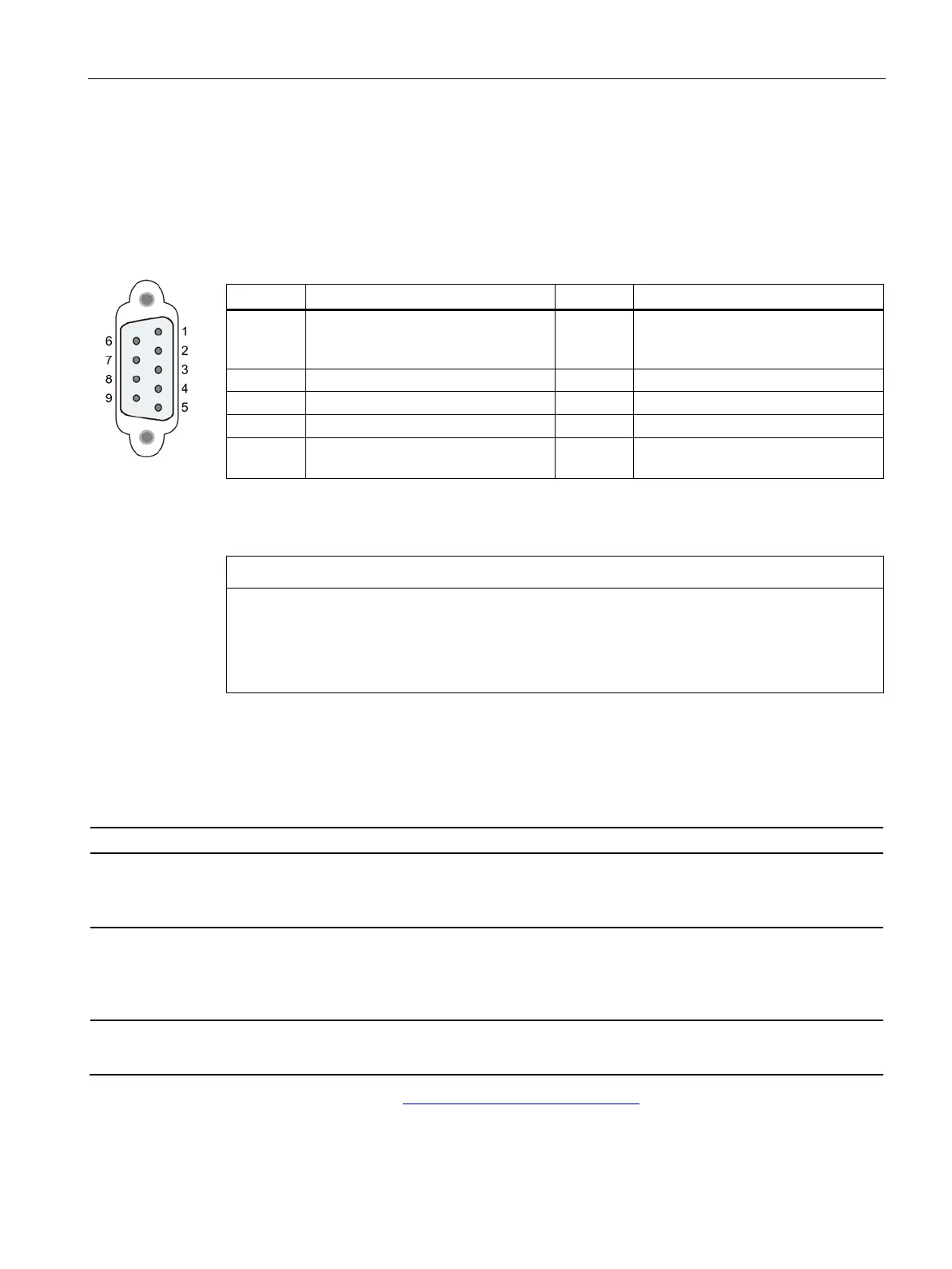
PROFIBUS interface
Table 6- 1 Pinout of the D-sub socket
1 - not used - 6 VP: Power supply +5 V only for bus
terminating resistors;
not for supplying external devices
5 DGND: Ground for data signals and
Housing Ground connector
PROFIBUS cable and connector
Contacting the shield of the PROFIBUS cable
The shield of the PROFIBUS cable must be contacted.
To do this, strip the insulation from the end of the PROFIBUS cable and connect the shield
to functional earth.
6.5 Permitted cable lengths - Ethernet
Permitted cable lengths - Ethernet
Alternative combinations per length range
0 ... 55 m
• Max. 55 m IE TP Torsion Cable with IE FC RJ45 Plug 180
• Max. 45 m IE TP Torsion Cable with IE FC RJ45 + 10 m TP Cord via
IE FC RJ45 Outlet
0 ... 85 m
• Max. 85 m IE FC TP Marine/Trailing/Flexible/FRNC/Festoon/Food Cable with
IE FC RJ45 Plug 180
• Max. 75 m IE FC TP Marine/Trailing/Flexible/FRNC/Festoon/Food Cable +
10 m TP Cord via IE FC RJ45 Outlet
0 ... 100 m
• Max. 100 m IE FC TP Standard Cable with IE FC RJ45 Plug 180
• Max. 90 m IE FC TP Standard Cable + 10 m TP Cord via IE FC RJ45 Outlet
See also Siemens Mall: (https://mall.industry.siemens.com)