Installation, wiring, commissioning
3.3 Connecting
SIMATIC CC7
Operating Instructions, 10/2019, C79000-G8976-C503-02
43
4. CC716:
If necessary, connect the cable for the digital input/output to the terminal block of the
device.
– Always wire the digital input and output in pairs.
– The maximum permitted cable length is 30 m.
For information on the position of the terminals, see section Digital Input / Output
(CC716) (Page 26).
5. Turn the power supply on only after the device has been completely wired and
connected.
The further procedure is described in the section Commissioning (Page 44).
Terminal blocks for digital input/output and power supply
The plug-in terminal blocks for the sockets have mechanical reverse polarity protection.
You can find additional technical details in the section Technical specifications (Page 125).
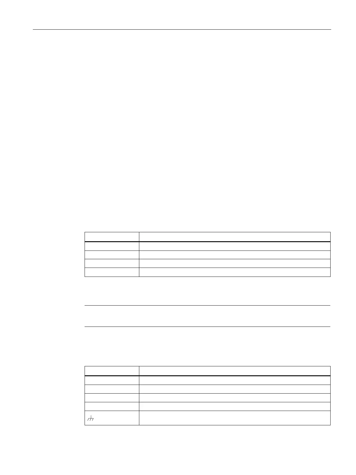
Digital input/output (CC716)
Table 3- 1 Assignment of the sockets for the digital input (DI) and digital output (DQ)
DO- -
Power supply
Note
The power supply unit of the device is not electrically isolated.
Use only copper cables for the power supply.
Table 3- 2 Pin assignment of the socket for the power supply
Ground reference for redundant connection
24 V DC for redundant connection (optional)
Functional earth