Operator elements and displays
5.1 Mobile Panel
Mobile Panel 177 (WinCC flexible)
5-4 Operating Instructions (Compact), Edition 07/2005
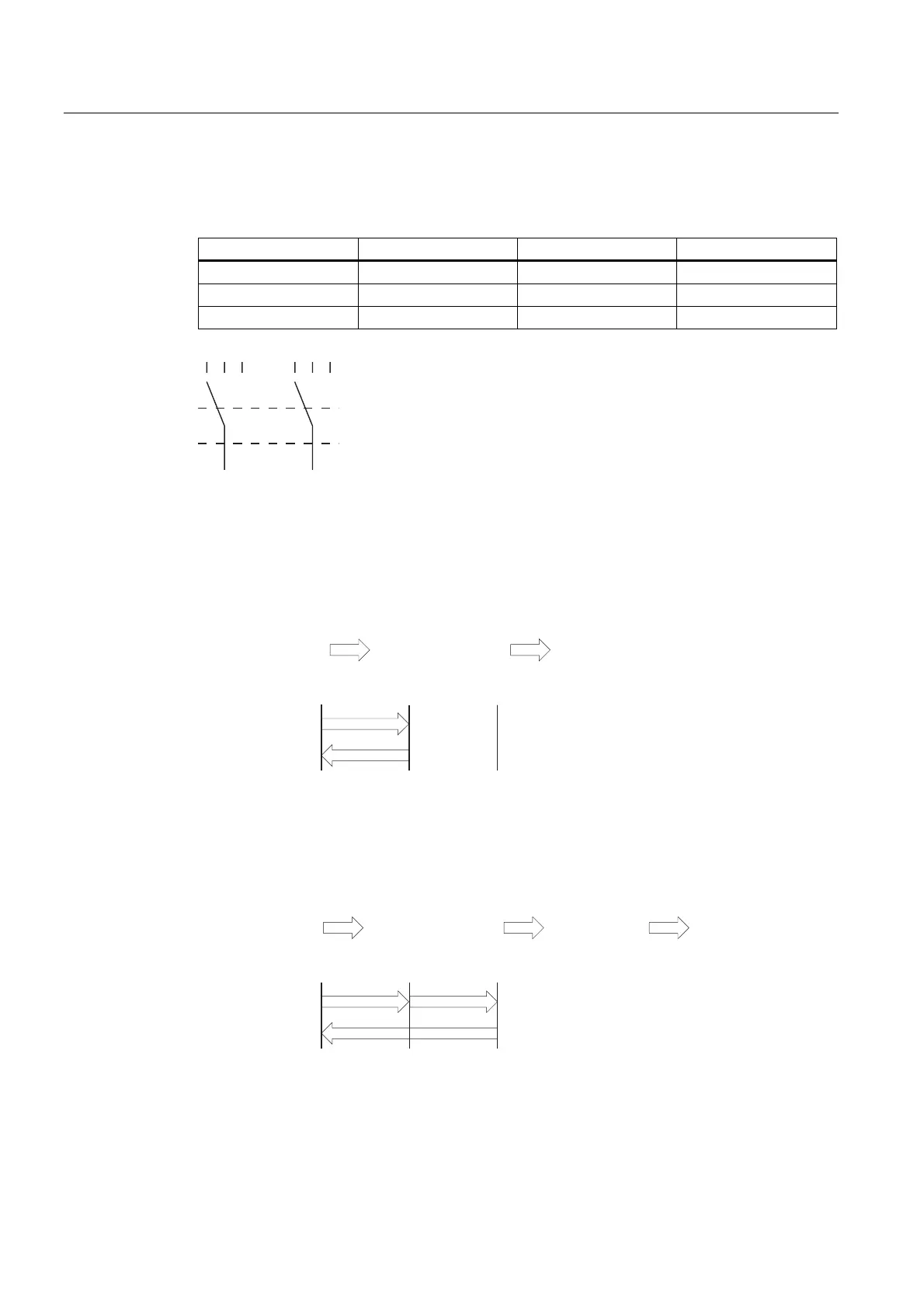
Switch settings
The primary function of the evaluating logic is to recognize the three switch settings:
Switch setting Function Enable switch Switch state
1 Neutral position Not activated OFF (open)
2 Enable Activated ON (closed)
3 Panic Pressed OFF (open)
(6 (6 (6(QDEOHVZLWFK
Figure 5-3 Switch settings of enabling switch
When the enabling switch is activated, the following switch sequences are possible:
Normal activation
(6(QDEOHVZLWFK
1HXWUDOSRVLWLRQ
(6(6
6ZLWFKVHWWLQJ
(6(6
(QDEOH
1HXWUDOSRVLWLRQ
[\
[
\
Figure 5-4 Interlinking of switch settings for normal operation
Panic activation
If the operator has pressed the enabling switch through to the "Panic" setting, the "Enable"
setting will be skipped when the switch is released.
(6(QDEOHVZLWFK
1HXWUDOSRVLWLRQ
(6(6
6ZLWFKVHWWLQJ
(6(6
(QDEOH
3DQLF 1HXWUDOSRVLWLRQ
[X\
[X
\
Figure 5-5 Interlinking of switch settings for panic activation
The signals of the enabling switch are fed to the terminal box via the connecting cable. For
manual special operating modes, these signals must be interconnected from the terminal
box to the safety circuit using two channels for power interruption.