Detailed descriptions
16.1 Motherboard
SIMATIC IPC647C
152 Operating Instructions, 12/2010, A5E02669337-02
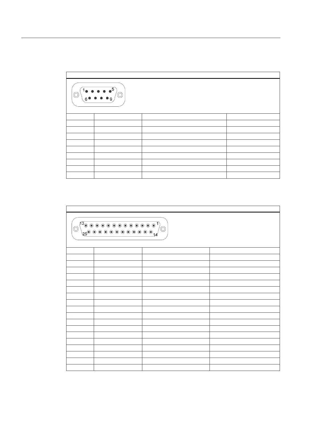
Serial interfaces COM1, COM2 (V24), X617, X615
Serial interface
Pin no. Short name Meaning Input / output
1 DCD (M5) Receive signal (carrier) Input
2 RxD (D2) Receive data Input
3 TxD (D1) Send data Output
4 DTR (S1) Data terminal ready Output
5 GND (E2) Functional ground (reference potential) –
6 DSR (M1) Ready for operation Input
7 RTS (S2) Request to send Output
8 CTS (M2) Clear to send Input
9 RI (M3) Incoming call Input
Parallel interface LPT1, X609
Parallel interface
Pinno. Short name Meaning Input / output
1 / Strobe (CLK) Data message Output (open collector)
2 Data - Bit 0 Data channel 0 Output (TTL level)
3 Data - Bit 1 Data channel 1 Output (TTL level)
4 Data - Bit 2 Data channel 2 Output (TTL level)
5 Data - Bit 3 Data channel 3 Output (TTL level)
6 Data - Bit 4 Data channel 4 Output (TTL level)
7 Data - Bit 5 Data channel 5 Output (TTL level)
8 Data - Bit 6 Data channel 6 Output (TTL level)
9 Data - Bit 7 Data channel 7 Output (TTL level)
10 /ACK Data acknowledge Input (4.7 kΩ pull up)
11 BUSY Not ready Input (4.7 kΩ pull up)
12 PE (PAPER END) Paper end Input (4.7 kΩ pull up)
13 SELECT Device selection Input (4.7 kΩ pull up)
14 / AUTO FEED Automatically new line Output (open collector)
15 / ERROR Device error Input (4.7 kΩ pull up)
16 / INIT Reset / Initialization Output (open collector)
17 / SELECT IN Printer selection Output (open collector)
18 – 25 GND Ground –