Features and functions 09/02
CP 243-1
18 J31069-D0428-U001-A1-7618
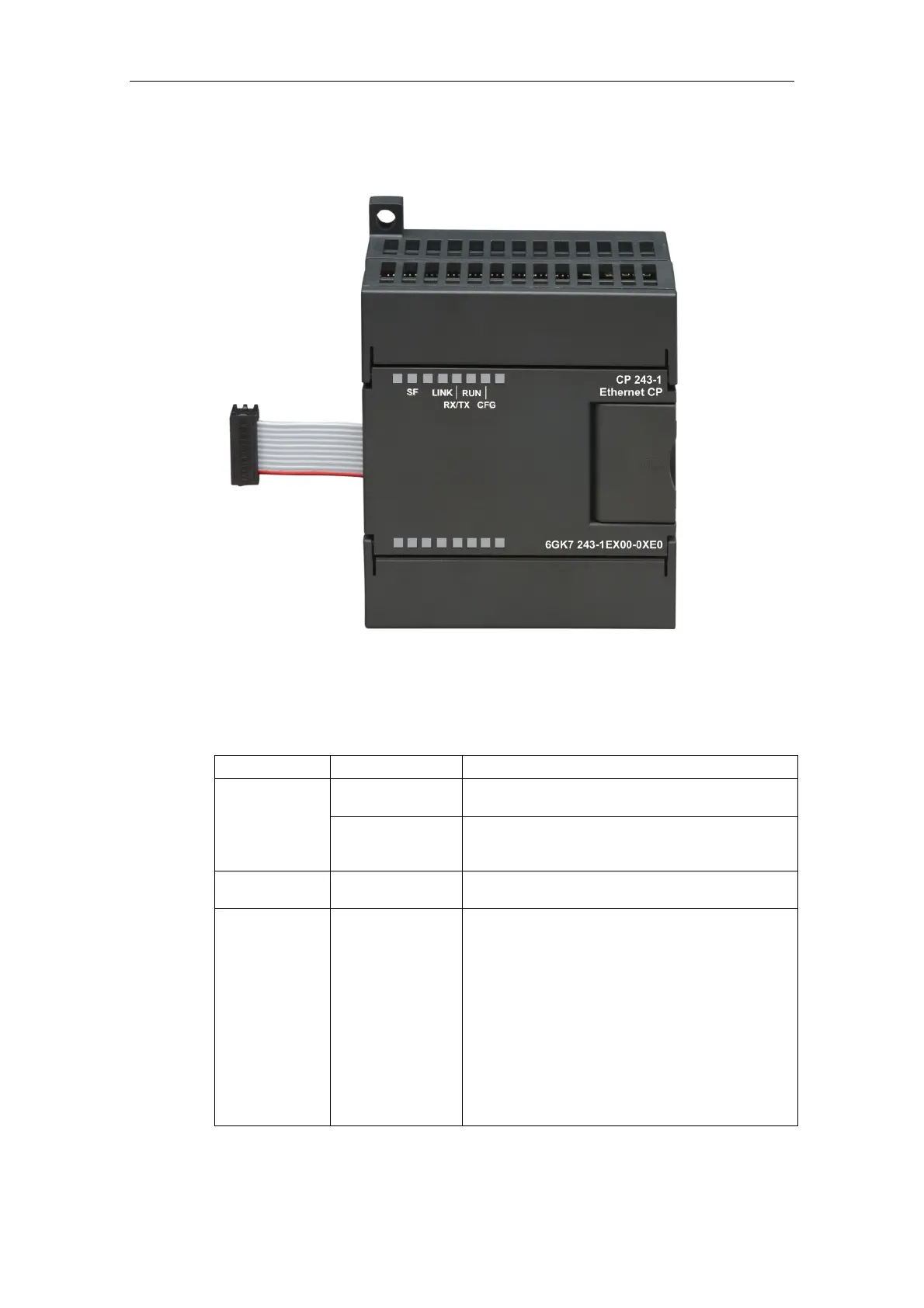
2.5 Displays: Front LEDs
Fig. 3. Front with LED displays
Five LEDs are located on the front to indicate:
LED display Color Meaning
Red, continuous
System error:
Lights up when an error occurred
SF
Red, flashes
System error:
Flashes (approx. every second), if the configuration
is faulty and a BOOTP server cannot be found.
LINK Green, continuous
Connection via the RJ45 interface:
Ethernet connection has been established
RX/TX Green, flickering Ethernet activity:
Data are being received and transmitted via the
Ethernet
Note:
A packet received via the Ethernet is not necessarily
intended for the CP 243-1. The CP 243-1 initially
accepts every packet transmitted on the Ethernet.
Only then does it decide whether the package is in-
tended for it.
The RX/TX LED also flashes as soon as the
CP 243-1 attempts to send a packet if the Ethernet
cable has been unplugged.
 Loading...


