09/02 Configuration
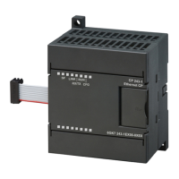
CP 243-1
J31069-D0428-U001-A1-7618
41
Byte offset in
variables mem-
ory
Description Data format Example
S7 connection 6 section (If not all bytes are used in this section, they should be filled in with
16#00)
83 Flag byte
See S7 connection 0 section.
1 byte hex See S7 connection 0
section.
84-87 IP address of partner
See S7 connection 0 section.
4 bytes hex See S7 connection 0
section.
88-89 Local TSAP 2 bytes hex 16#1600
90-91 Remote TSAP 2 bytes hex See S7 connection 0
section.
S7 connection 7 section (If not all bytes are used in this section, they should be filled in with
16#00)
92 Flag byte
See S7 connection 0 section.
1 byte hex See S7 connection 0
section.
93-96 IP address of partner
See S7 connection 0 section.
4 bytes hex See S7 connection 0
section.
97-98 Local TSAP 2 bytes hex 16#1700
99-100 Remote TSAP 2 bytes hex See S7 connection 0
section.
STEP 7 Micro/Win Server section
101 Flag byte
Bit [0] Server
0: Server
1: Not supported
Bit [1] Keep Alive
0: No Keep Alive support
1: Keep Alive support
Bit [2-6] Not in use
Bit [7] Section valid
0: Not supported
1: Section in use
1 byte hex 16#82:
Server, Keep Alive
support,
the STEP 7 Micro/WIN
Server section is in
use and contains valid
data.
102-105 Internal use 4 bytes hex
CRC section
106-107 CRC over all CDB bytes without the
CRC section itself
2 bytes hex
Table 3: CDB structure

 Loading...


