Description of the device
2.3 Properties and functions
Optical link module
Operating Instructions, 01/2020, C79000-G8976-C270-06
11
2.3 Properties and functions
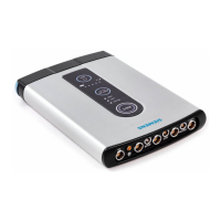
Device design
Every module has two (OLM P11, G11), three (OLM P12, G12) or four (OLM P22, G22)
independent channels (ports) that consist of a transmitter and a receiver part.
The power supply voltage for operation is 24 VDC. To increase operational reliability, a
redundant power supply is possible.
Channels
Electrical channels
The electrical channel is designed as a 9-pin D-sub female connector. An RS-485 bus
segment complying with the PROFIBUS standard EN 50170 /2/ can be connected to this
channel.
Optical channels
The fiber-optic cables are connected via BFOC/2.5 connectors.
Seven multicolor LEDs indicate the current operating mode and any disruptions as well as
the level ratios on the optical interfaces.
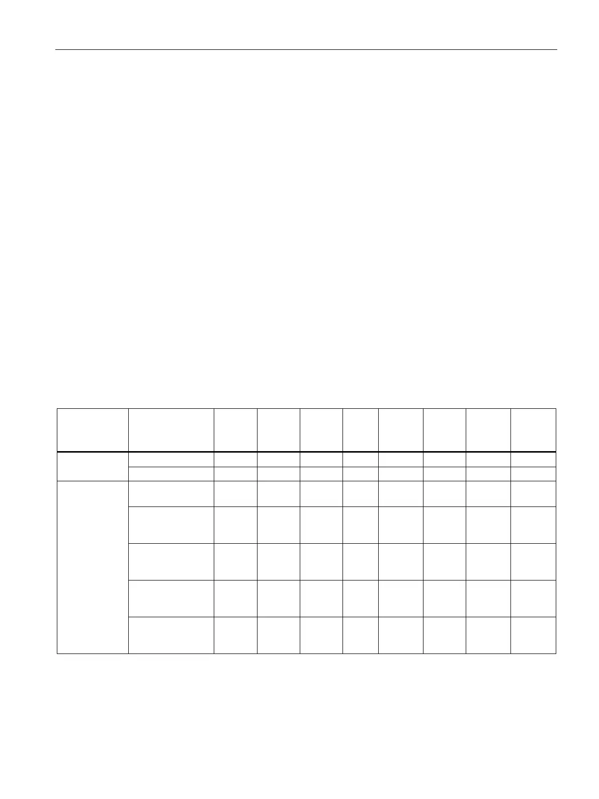
The following table shows the various connection options of the modules and the maximum
possible optical ranges of the individual channels.
Number of
channels
Usable fiber
types
Plastic FO cable
80 m 80 m 80 m - - - - -
PCF FO cable fiber
(HCS
®
FO cable)
400 m 400 m 400 m - - - - -
Quartz glass FO
cable
1
- - - - - - 15 km 15 km
Quartz glass FO
cable
2
- - - 3 km 3 km 3 km - -
Quartz glass FO
cable
2
- - - 3 km 3 km 3 km - -
Number of electrical and optical ports per module, usable fiber types as well as the maximum achievable fiber
-optic cable
distances between two modules. For the precise conditions of use, refer to the section "Technical specifications".
Single mode fiber