Description of the device
2.2 Device view of an OLM
Optical link module
10 Operating Instructions, 01/2020, C79000-G8976-C270-06
2.2 Device view of an OLM
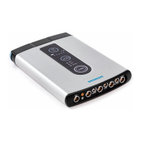
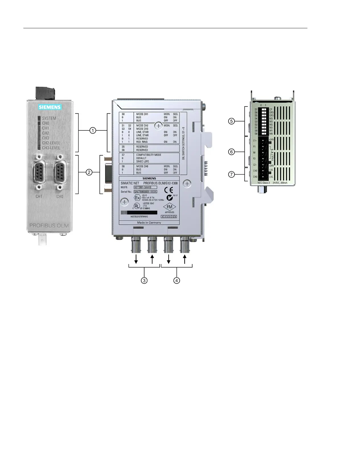
The following figure shows a PROFIBUS OLM with all interfaces, display elements and
setting options.
Channel 2 (optical)
• Transmitter (left)
• Receiver (right)
Channel 3 (optical)
• Transmitter (left)
• Receiver (right)
DIL switch for setting the modes
Operating voltage L1+/M/L2+
Sockets for measuring the levels of the optical interfaces
Figure 2-1 View from the front, side and top