


Do you have a question about the Siemens SIMATIC NET and is the answer not in the manual?
Explains hazard symbols and their meaning to ensure personal safety and prevent property damage.
Defines qualified personnel and their responsibilities for operating the product safely.
Provides essential notes for the correct and safe use of Siemens products.
Explains how the operating instructions support the commissioning of PROFIBUS OLM devices.
Lists the specific SIMATIC NET OLM devices to which these instructions apply.
Identifies the intended personnel for commissioning PROFIBUS networks with OLM series.
Guides users on how to quickly find information using aids like the table of contents.
Provides links to additional SIMATIC NET manuals, online support, and glossaries.
Outlines the steps for unpacking and inspecting the device for completeness and damage.
Details Siemens' approach to industrial security and recommendations for product updates.
Lists the available SIMATIC NET OLM devices with their corresponding article numbers.
Explains the meaning of the different parts of the OLM type designation.
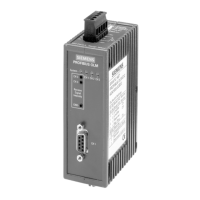
Provides a visual diagram of the PROFIBUS OLM, highlighting interfaces and controls.
Details the device design, electrical, and optical channels, including fiber types.
Explains core functions, notes on BFOC/PCF connectors, and mechanical construction.
Describes the use of PROFIBUS OLMs for converting electrical to optical interfaces.
Introduces the LED display system and explains the 'SYSTEM' LED status.
Details the meaning of LED colors and statuses for electrical channels CH1 and CH0.
Explains the LED statuses for optical channels CH2 and CH3 in various modes.
Describes the function of the CH2-LEVEL and CH3-LEVEL LEDs for signal quality.
Lists essential preparation steps including unpacking, acclimatization, and topology selection.
Details the sequence for commissioning the OLM, including DIL switches and connections.
Illustrates the default positions of the DIL switches for factory configuration.
Explains how DIL switch S7 enables functional compatibility with older SINEC L2FO OLMs.
Details how to set operating modes for electrical channels CH1 and CH0 using DIL switches.
Explains how to set modes for optical channels CH2 and CH3 using DIL switches S1-S4.
Describes how to adjust transmit power for channels CH2 and CH3 using DIL switches S5/S6.
Provides information on using PCF and plastic fibers, and managing optical overdrive.
Details DIL switch functions for specific OLM models and mixed operations.
Provides critical warnings regarding ambient temperature, pollution degree, and hazardous environments.
Offers advice on electromagnetic compatibility and suppressing switching inductances.
Details how to reduce interference by maintaining clearances and handling cable shields.
Provides instructions on securing braided shields using metal cable clamps for proper grounding.
Explains optical power budget, aging effects, and factors influencing link performance.
Outlines mounting options (DIN rail, wall) and prerequisites for installation.
Step-by-step instructions for installing and removing the OLM from a 35 mm DIN rail.
Instructions for mounting the OLM on a wall or cabinet plate using a mounting plate.
Details safety requirements (SELV, LPS, NEC Class 2) for the power supply unit.
Provides warnings and precautions for connecting equipment in potentially explosive atmospheres.
Guidance on using shielded twisted pair cables, connectors, and termination for RS-485 bus.
Details the 9-pin D-sub connector pin assignment for RS-485 interfaces.
Information on connecting the module to a stabilized 24 VDC power supply, including redundancy.
Explains the relay with floating contacts for signaling faults and errors in the network.
Describes how to measure optical receive levels using a voltmeter and PLC inputs.
Provides a diagram and criteria for estimating bus traffic quality based on measured levels.
Step-by-step guide for connecting optical cables using BFOC/2.5 connectors.
Lists supported network topologies: point-to-point, bus, star, and redundant optical ring.
Provides guidelines for connecting segments, handling noise, and wavelength matching.
Details how to implement a bus topology using OLMs connected by two-fiber cables.
Explains the mode for segmenting disrupted fiber-optic links and its monitoring mechanisms.
Describes the mode for connecting to components that do not support frame echo monitoring.
Details setting up an active PROFIBUS star coupler and general guidelines.
Explains the redundant optical ring for high reliability and its implementation with two optical channels.
Outlines essential settings like HSA, retry values, and slot time for correct ring operation.
Presents two configurations for setting up a redundant optical ring using two OLMs.
Describes how LEDs indicate status and faults in redundant optical ring topologies.
Explains the importance of 'Slot Time' and how to configure bus/star topologies.
Provides formulas and tables for calculating slot time based on data rate and network parameters.
Instructions for cleaning the device using a dry, lint-free cloth, avoiding liquids and dirt ingress.
Warns about chemicals damaging sealing components and advises on device checks.
States OLMs are maintenance-free, describes fuse behavior, and advises on chemical contact.
Refers to LED display descriptions for troubleshooting System LED errors.
Guides on checking DIL switches and RS-485 connections for CH1/CH0 LED errors.
Provides steps to check optical connections, fiber types, and LED status for CH2/CH3.
Explains how to interpret yellow/red level displays and how to simulate a green display.
Lists general properties like operating voltage, current consumption, and signaling contact data.
Details transmission speed, bit error rate, and signal delay times for the OLM.
Provides data on wavelength, launchable optical power, and coverable distances for different fiber types.
Lists standards and test levels for radiated emission, conducted emission, and surge immunity.
Specifies operating temperature, humidity, oscillation, and shock resistance data.
Includes degree of protection, dimensions, housing material, and MTBF values.
Provides front view drawings with key dimensions indicated in millimeters.
Shows side (left/right) and top views of the OLM with relevant dimensions.
Explains how to check for issued approvals based on markings on the device's type plate.
Clarifies that devices are not machines and must be included in machine conformity procedures.
Lists compliance with EC directives (ATEX, EMC, RoHS) and harmonized standards.
Details ATEX classification, certificate numbers, and relevant standards for protection types.
Provides IECEx classifications, certificate numbers, and standards for protection types.
Confirms compliance with EMC directive and RoHS restrictions on hazardous substances.
Lists FM, cULus, and Australian RCM standard compliance details.
Mentions shipbuilding approvals and compliance with FDA/IEC laser safety requirements.
Provides a glossary of abbreviations and acronyms used throughout the document.
Lists relevant literature and standards referenced in the operating instructions.
| Category | Industrial Communication Software |
|---|---|
| Manufacturer | Siemens |
| Operating Systems | Windows, Linux |
| Protocols Supported | PROFIBUS, PROFINET, OPC UA |
| Compatibility | Siemens PLCs, Third-party devices with supported protocols |




 Loading...