Description of the device
2.5 LED display
Optical link module
Operating Instructions, 01/2020, C79000-G8976-C270-06
15
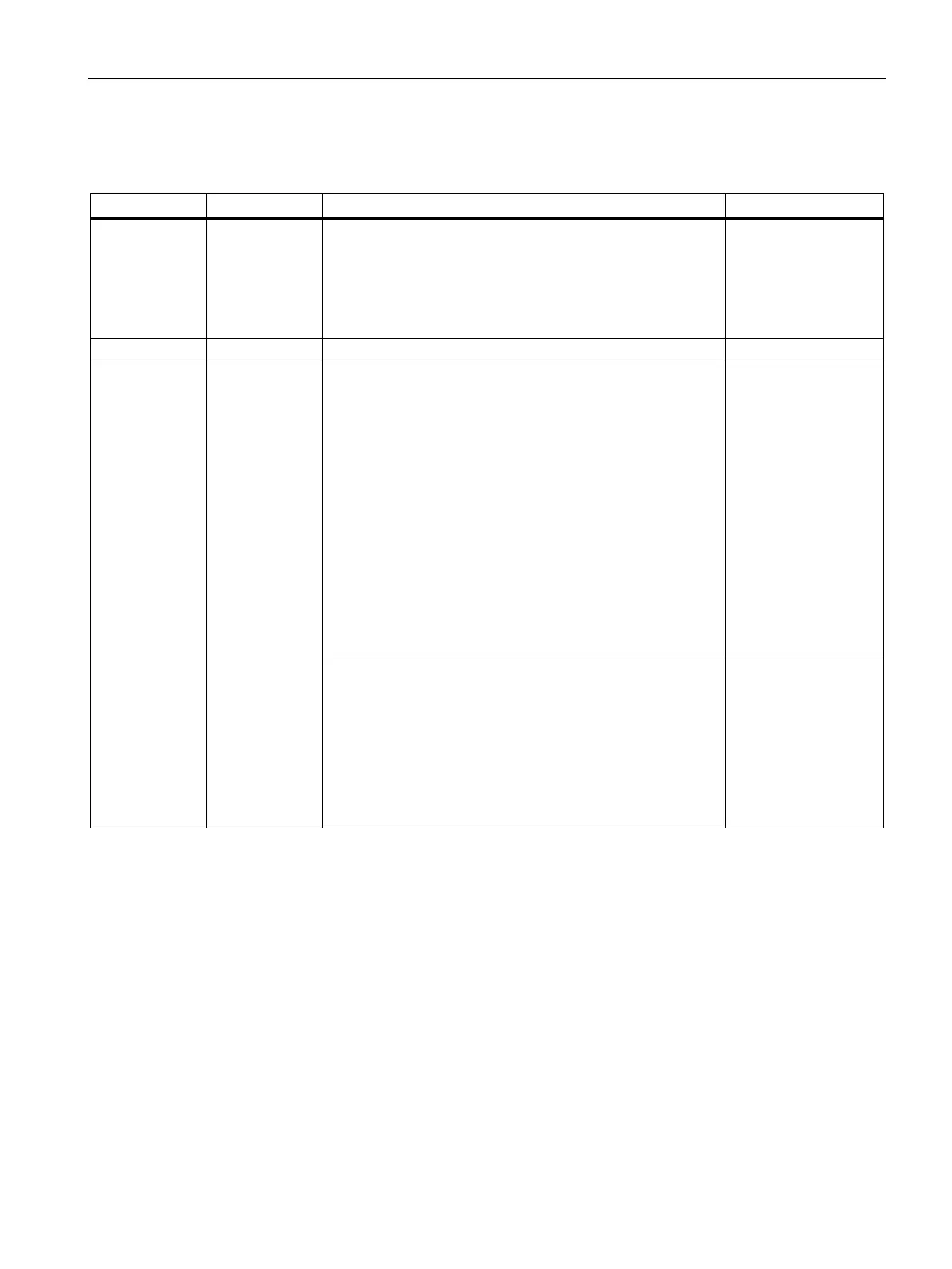
2.5.3 LED "CH1"/"CH0" - electrical
- Off Bus node is not connected, because:
• Connected bus node is not turned on
• Interruption
1
of one or both wires of the RS-485 bus cable
• Short-circuit
1
or ground fault of the wires of the RS-485
bus cable
Does not signal
Signals are being received on the RS-485 bus cable.
Red Flashing/lit Sporadic disturbances because of
• Inadequate shielding of the RS-485 bus cable
• Open bus cable, this means the RS-485 bus cable is only
connected to the module at one end
• RS-485 segment is not terminated or only at one end
• Pulling/plugging an RS-485 bus terminal or terminating
plug
Permanent disturbance due to:
• Wires A and B of the RS-485 bus cable have been
swapped over
• Short-circuit
1
on the RS-485 bus cable
• Transmission time exceeded due to a bus node in a bus
segment connected to channel 1 or 0
Signals
Permanent disturbance due to:
• Module and another bus node connected over channel 1
or 0, transmit at the same time (e.g. because of duplicate
address assignment or slot time set too low or when can-
celing segmentation in the optical bus, see section "Bus
topology (Page 54)")
• RS-485 driver of the module is faulty (e.g. following a
lightning strike)
Does not signal
Depends on the cable length between the RS-485 interface and the problem and on the baud rate.
It can vary from one example to another.