Connection
6.5 Connecting optical cables
Optical link module
Operating Instructions, 01/2020, C79000-G8976-C270-06
51
6.5 Connecting optical cables
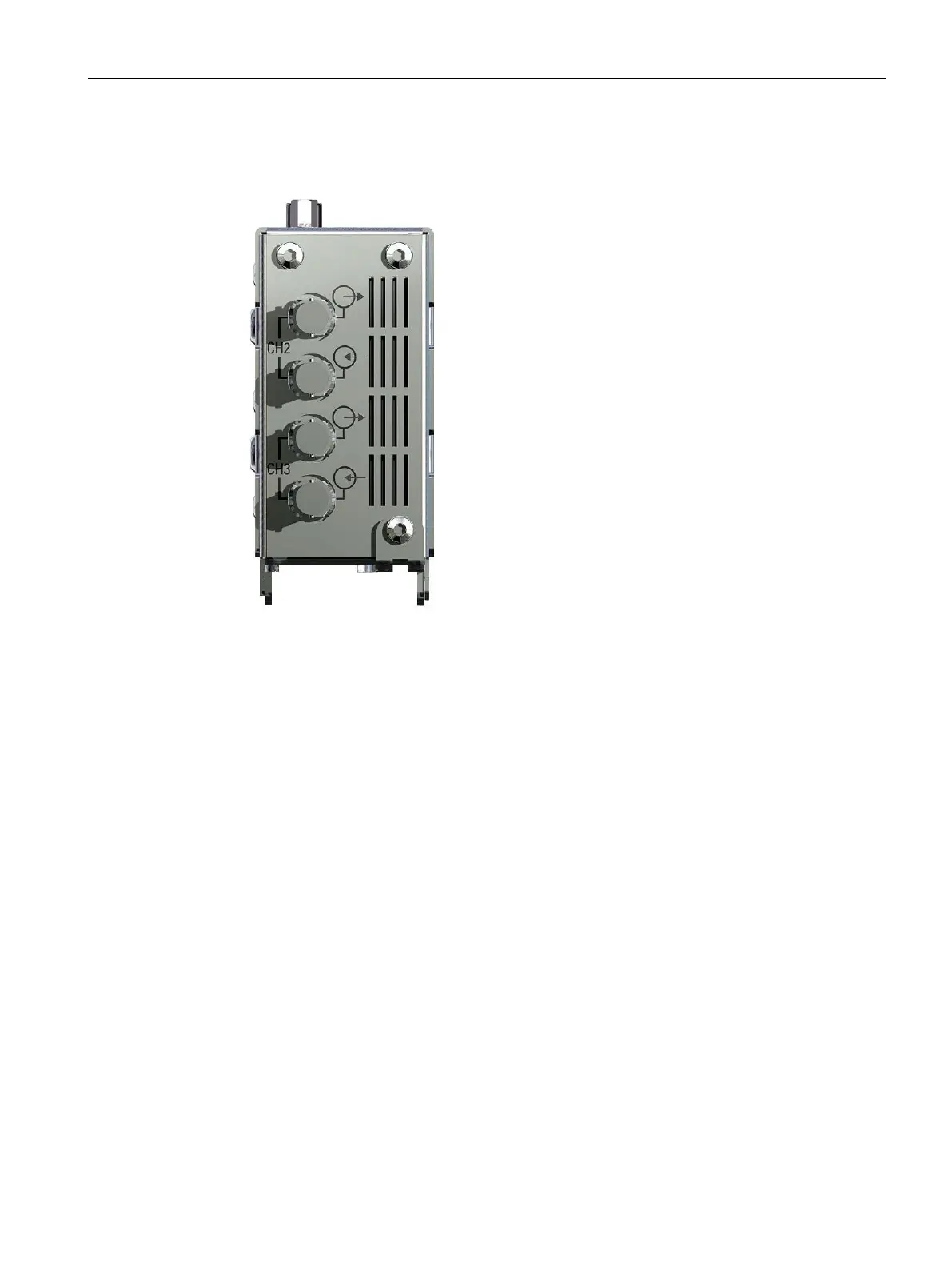
Figure 6-2 View of the module from below with optical channels 2 and 3 (device with two optical
channels)
Follow the steps below to connect the optical cables:
1. Connect the single modules via a two-core fiber-optic cable with BFOC/2.5 connectors.
2. Note the following:
– The end faces of the optical connectors must be free of any contamination.
– One optical input and one optical output must be interconnected (“crossover
connection“). The BFOC sockets of a channel that belong together are marked on the
lower part of the front panel.
– The optical connector is securely locked to the BFOC socket. The bayonet connector
must be locked home.
– The tip of the BFOC connector must be inserted completely into the FO cable socket
when using single mode fiber-optic cables. If necessary, push the connector into the
socket using anti-kink sleeve to make reliable contact.
3. Provide adequate strain relief for the fiber-optic cable and remember the minimum bend
radii of the FO cable, see note below.