Connection
6.1 Electrical RS-485 bus cables
Optical link module
Operating Instructions, 01/2020, C79000-G8976-C270-06
45
Information on RS-485 bus cables
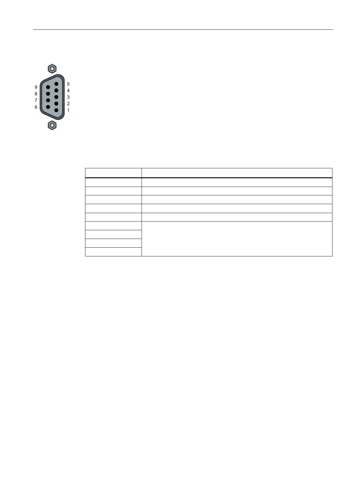
● The modules are equipped with one or two electrical ports with the RS-485 level.
● They are designed as a 9-pin D-sub female connector with screw locking mechanism
(inner thread UNC 4-40).
● The RS-485 interfaces are galvanically connected to the housing.
● The pin assignment corresponds to the PROFIBUS standard assignment.
– A short-circuit proof 5 V output for the supply of external pull-up/pull-down resistances
is available at pin 6.
The resistances must have a power loss of at least 0.25 W.
– The RS-485 bus cables RxD/TxD, N and RxD/TxD, P are galvanically isolated from
the 24 V supply voltage within the SELV limits (functional isolation).
6 +5 V output
Not used
Note on compatibility
In the OLM V3 modules, pin 2 was additionally connected to ground and pin 1 to the shield.
This does not conform to the relevant standard EN 50170 /2/. This presents no problem,
when cables complying with the PROFIBUS standard are used.
When installing the module in an existing cabling system, check the pin assignment. If
necessary, change the pin assignment.