Service and maintenance
12.1 Diagnostics
SIMATIC RF185C, RF186C, RF188C, RF186CI, RF188CI
146 Operating Instructions, 04/2020, C79000-G8976-C512-03
12.1.1 Diagnostics via the LED display
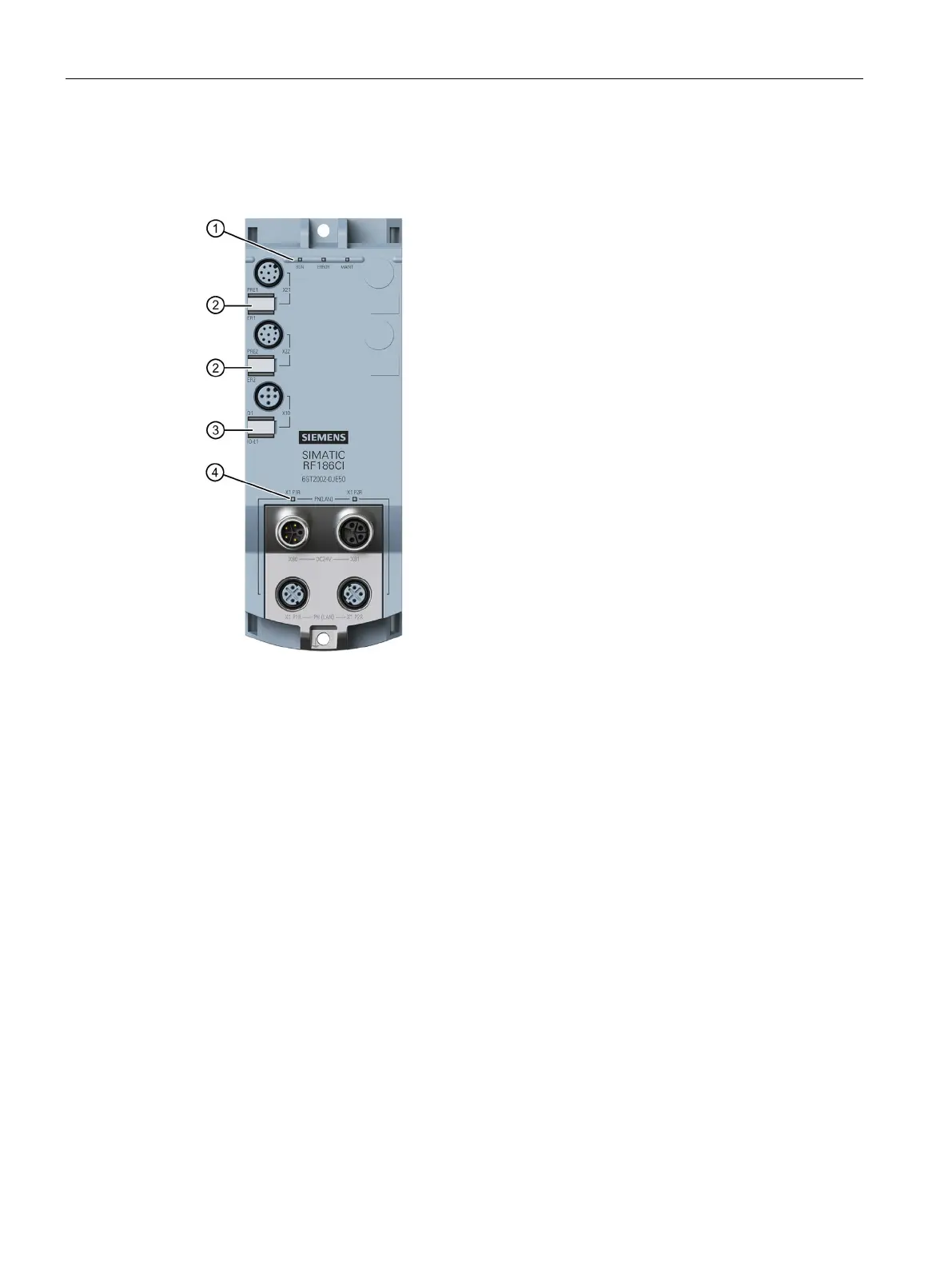
The following figure shows the LEDs of the RF18xC/RF18xCI in detail.
• RUN/STOP (RUN)
Indicates whether the CM is ready for operation.
• ERROR (ERROR)
Indicates whether an error has occurred.
• MAINTENANCE (MAINT)
Shows whether the communication module needs mainte-
• PRESENCE (PRE)
Indicates whether there are one or multiple transponders in
• ERROR (ER)
Indicates whether communication with the reader is taking
place and whether a reader error has occurred.
• Channel status (Q1)
Indicates whether the output is switched on.
• Channel fault (IO-L1)
Indicates whether an IO-Link device is connected and wheth-
er an error has occurred.
PROFINET/Ethernet LED display
• LINK P1 (X1 P1R)
Indicates that there is a link via the Ethernet interface "1".
• LINK P2 (X1 P2R)
Indicates that there is a link via Ethernet interface "2".
Figure 12-1 LED displays of the RF18xC/RF18xCI communication module