Connection
5.5 Connecting the communications module
SIMATIC RF185C, RF186C, RF188C, RF186CI, RF188CI
40 Operating Instructions, 04/2020, C79000-G8976-C512-03
5.5 Connecting the communications module
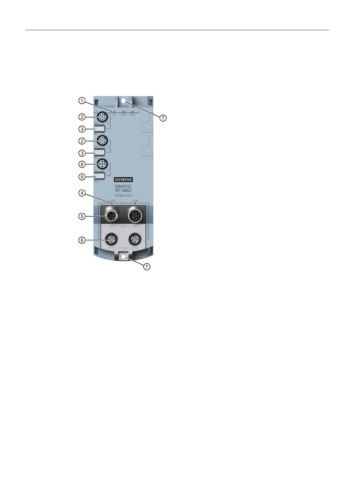
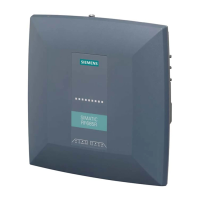
Interfaces
Status LEDs
2x interfaces for PROFINET IO
X1 P1R, X1 P2R
Reader interfaces
X21-X24
Mounting holes and functional ground
Reader LEDs
I/O interface
1)
X10
1)
2x interfaces for the power supply
X80, X81
Figure 5-10 Design of the communication module
1)
The I/O interface and the associated LEDs are only a feature of the CI devices.
You can loop the supply voltages and PROFINET IO via the M12 round sockets
⑤ + ⑥.
The pin assignments of the various interfaces are lasered on the side of each
communication module at the factory.