Connection
5.5 Connecting the communications module
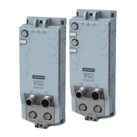
SIMATIC RF185C, RF186C, RF188C, RF186CI, RF188CI
42 Operating Instructions, 04/2020, C79000-G8976-C512-03
Wiring interfaces/connectors
The following tables show the pin assignment for the interfaces/connectors.
Table 5- 2 Pin assignment PROFINET IO; M12 socket (4-pin, D-coded)
View of M12 socket, 4-pin
4 Data line RxN
Table 5- 3 Pin assignment power supply; M12 socket (4-pin, L-coded)
View of M12 socket, 4-pin
2 N2: 0 V load supply (white)
Relevant for RF18xCI devices
4 L2: +24 V (black)