Rule 2: The output of a complex ele-
ment (memory, comparator, timer and
counter) must not be
ored.
Fig. 12: Only AND boxes are allowed in.CSFs after a complex element.
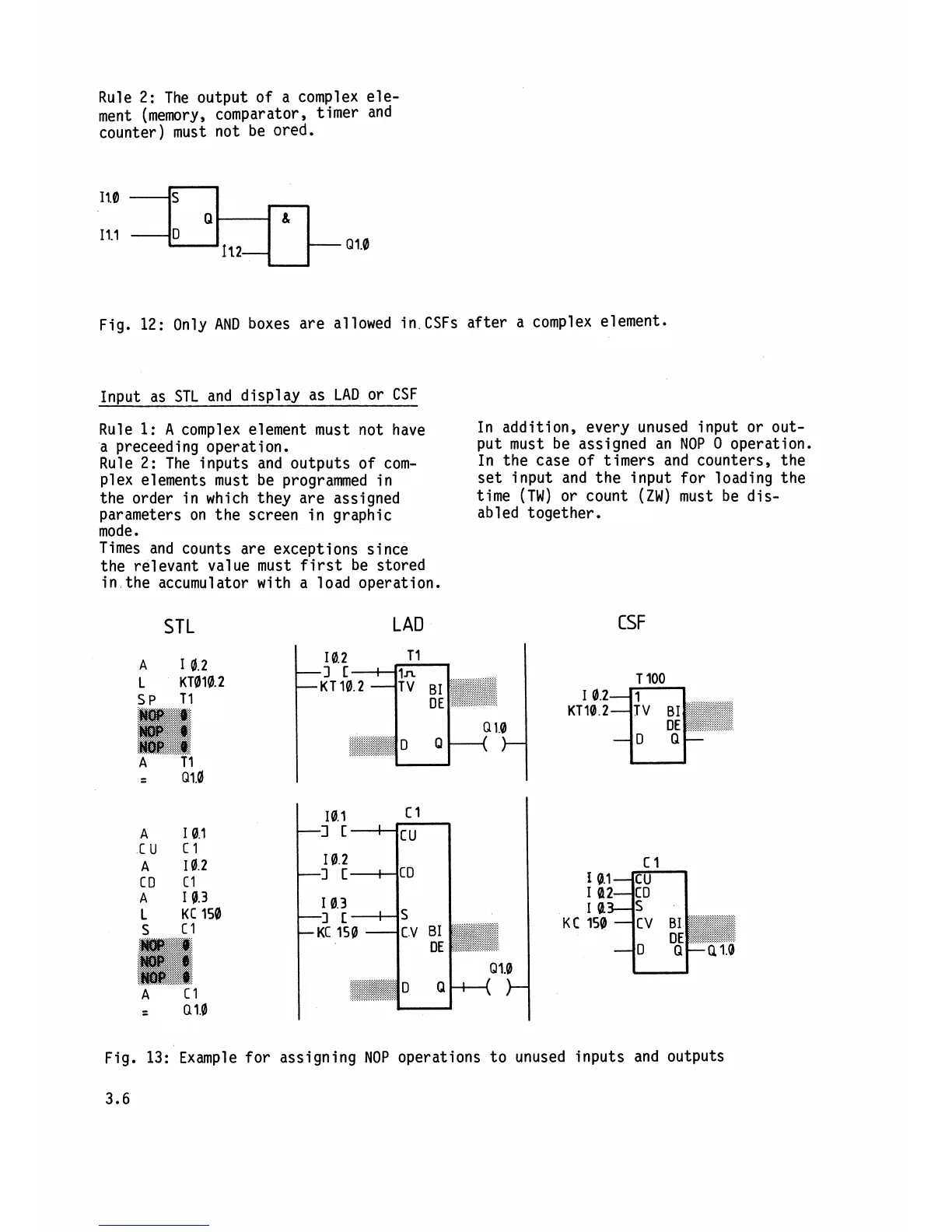
In~ut as STL and display as LAD or CSF
Rule
1:
A
complex element must not have
In addition, every unused input or
out-
a preceed
i
ng operation.
put must be assigned an NOP
0 operation.
Rule 2: The inputs and outputs of
com-
In the case of timers and counters, the
plex elements must be programmed in
set input and the input for loading the
the order in which they are assigned
time (TW) or count (ZW) must be
dis-
parameters on the screen in graphic
abled together.
mode.
Times and counts are exceptions since
the relevant value must first be stored
in the accumulator with a load operation.
STL
LAD
CSF
Fig. 13:
Example for assigning NOP operations to unused inputs and outputs