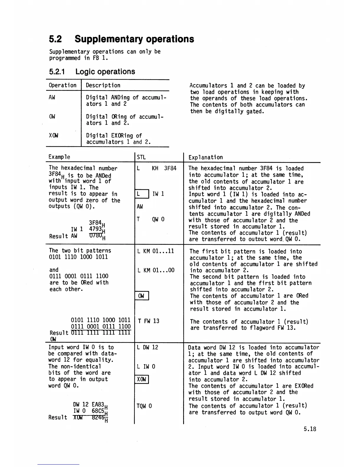
5.2
Supplementary operations
Supplementary operations can only be
programmed in
FB
1.
5.2.1
Logic
operations
Accumulators
1
and
2
can be loaded by
two load operations in keeping with
the operands of these load operations.
The contents of both accumulators can
then be digi tal ly
gated.
Operation
AW
OW
XOW
Description
Digital
ANDing of accumul-
ators
1
and
2
Digital ORing of accumul-
ators
1
and
2.
Digital EXORing of
accumulators
1
and
2.
Example
The hexadecimal number
3F84H
is to be ANDed
with input word
1
of
inputs
IW
1.
The
result is to appear in
Output word zero of the
outputs (QW
0).
3F84H
IW
3H
Result
AW
The two bit patterns
0101 1110 1000 1011
and
0111 0001 0111 1100
are to be ORed with
each other.
STL
L
KH
3F84
L ]IN1
AW
T
QW
0
L
KM
01...11
L
KM
01
...
00
Explanation
The hexadecimal number
3F84 is loaded
into accumulator
l;
at the same time,
the old contents of accumulator
1
are
shifted into accumulator
2.
Input word
1
(IW
1)
is loaded into ac-
cumulator
1
and the hexadecimal number
shifted into accumulator
2.
The con-
tents accumulator
1
are digitally ANDed
with those of accumulator
2
and the
result stored in accumulator
1.
The contents of accumulator
1
(result)
are transferred to
out~ut word.
QW
0.
The first bit pattern is loaded into
accumulator
1;
at the same time, the
old contents of accumulator
1
are shifted
into accumulator
2.
The second bit pattern is loaded into
accumulator
1
and the first bit pattern
shifted into accumulator
2.
The contents of accumulator
1
are ORed
with those of accumulator
2
and the
result stored in accumulator
1.
The contents of accumulator
1
(result)
are transferred to
flagword FW
13.
Data word DW
12
is loaded into accumulator
1;
at the same time, the old contents of
accumulator
1
are shifted into accumulator
2.
Input word
IW
0
is loaded into accumul-
ator
1
and data word
L
DW
12
shifted
into accumulator
2.
The contents of accumulator
1
are EXORed
with those of accumulator
2
and the
result stored in accumulator
1.
The contents of accumulator
1
(result)
are transferred to output word
QW
0.
0101 1110 1000 1011
0111 0001 0111 1100
Result
OW
Input word
IW
0
is to
be compared with data-
word
12
for equality.
The non-identical
bits of the word are
to appear in output
word
QW
0.
DW
12
EA83H
IW
0
68C5
Result
XCKTZR$
T
FW
13
L
DW
12
L
IW
0
xcu
l
TQW
0