1.
The
programming language
1.1
STEP
5
programming language
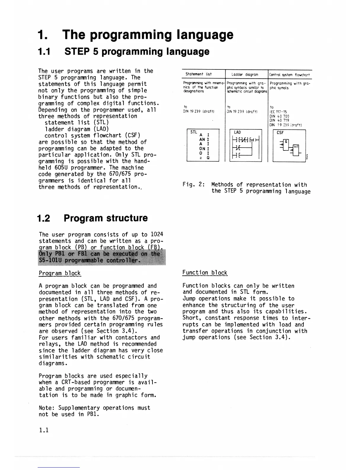
The user programs are written in the
STEP 5 programning language. The
statements of this
l
anguage permit
not only the programning of simple
binary functions but also the pro-
gramming of complex digital functions.
Depending on the programmer used, all
three methods of representation
statement list (STL)
1 adder d
i
agram (LAD)
control system flowchart (CSF)
are possible so that the method of
programming can be adapted to the
particular application. Only STL pro-
gramming is possible with the hand-
held 605U programmer. The machine
code generated by the 6701675 pro-
grammers is identical for all
three methods of representat ion
..
1.2
Program structure
The user program consists of up to
1024
statements and can be written as a pro-
gram block (PB) or function block (FB).
WFy
PBl
at
FBI
can
k
exwwted
on
%c
S5+1O1U
programable
contrallsr,
Program block
A program block can be programmed and
documented in
a11 three methods of re-
presentation (STL, LAD and CSF).
A
pro-
gram block can be translated from one
method of representation into the two
other methods with the 6701675 program-
mers provided certain programming rules
are observed (see Section
3.4).
For users famil far with contactors and
re1 ays, the LAD method is recommended
since the ladder diagram has very close
similarities with schematic circuit
diagrams.
Program blocks are used especially
when a CRT-based
programmer is avail-
able and programming or documen-
tation is to be made in graphic form.
Fig.
2:
Methods of representation with
the STEP 5 programming language
to
3lN
19 239
idrcftl
Function block
Function blocks can only be written
and documented in STL form.
Jump operations make
it
possible to
enhance the structuring of the user
program and thus also its capabilities.
Short, constant response times to inter-
rupts can be implemented with load and
transfer operations in conjunction with
jump operations (see Section
3.4).
Note: Supplementary operations must
not be used in
PB1.
+o
2lh
19 239
Idrcctl
to
KC
117-15
DIN
L3
705
DIN
40
719
DIN
19
23i
,
lrrlfti