Loading and transferring a time
(see also under timer and counter operations)
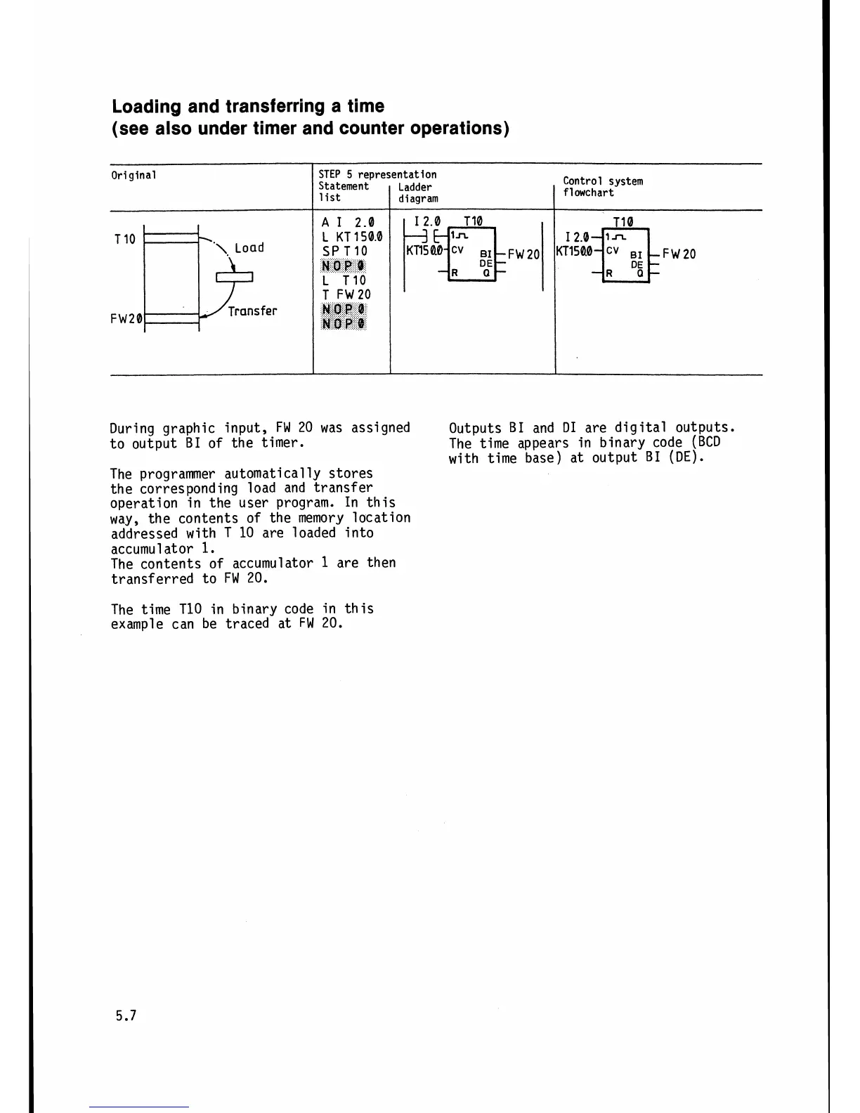
During graphic input,
FW
20 was assigned
Outputs
B1
and D1 are digital outputs.
to output
BI
of the timer.
The time appears in binary code
(BCD
with time base) at output
B1
(DE).
The programmer automatically stores
the corresponding load and transfer
operation in the user program. In this
way, the contents of the
memory location
addressed with T
10 are loaded into
accumul
ator
1.
The contents of accumulator
1
are then
transferred to
FW
20.
Original
T1orpoy
FW20
Transfer
The time T10 in binary code in this
example can be traced at
FW
20.
STEP
5
representation
Control system
flowchart
t(l!lk!~-~FW~o
Statement
list
A
I
2.0
i{iir.O
L
T10
T
FW20
MOP
Q
MOP
BI:
Ladder
diagram
pq-bFw20