5.1.4
Timer
functions
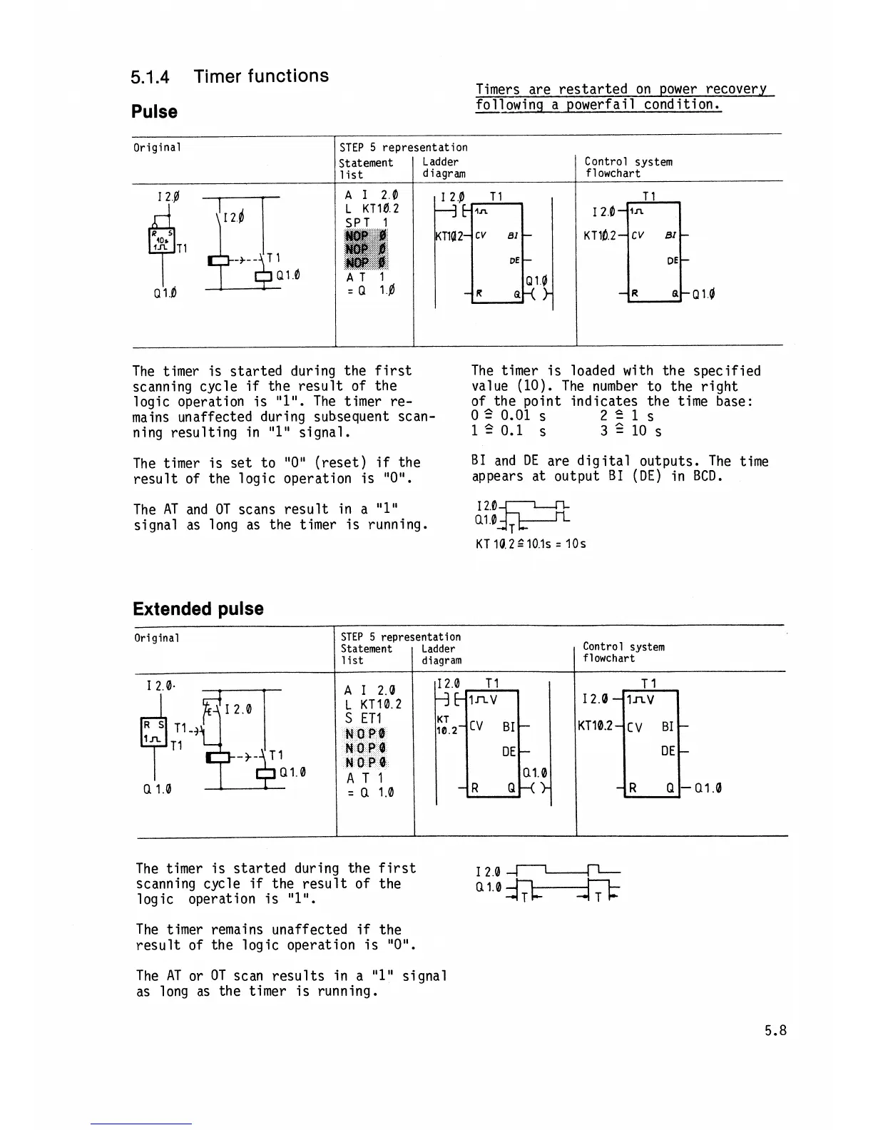
Pulse
Timers are restarted on power recovery
following a powerfail condition.
Original
The timer is started during the first
scanning cycle
if
the result of the
logic operation is
"l".
The timer re-
mains unaffected during subsequent scan-
ning resulting in
"1"
signal.
STEP
5
representation
The timer is set to "0" (reset)
if
the
result of the logic operation is
"0".
diagram
The AT and OT scans result in a
"1"
signal as long as the timer is running.
Control system
flowchart
The timer is loaded with the specified
value (10). The number to the right
of the point indicates the time base:
0
5
0.01
S
251s
120.1
S
3GlOs
B1
and
DE
are digital outputs. The time
appears at output
B1
(DE)
in
BCD.
Extended pulse
Original
A
I20
L
KT10
2
S
ET1
NOPB
NOPQ
NOPQ
AT1
=
Q
1.0
STEP
5
representation
Statement Ladder Control system
The timer is started during the first
scanning cycle
if
the result of the
I
2.0
J-L--v-
logic operation is
"It1.
Q1.O
&k-A-&
list
The timer remains unaffected
if
the
result of the logic operation is
"0".
The AT or OT scan results in a
"1"
signal
as long as the timer is running.
diagram
flowchart