"OFF"
delay
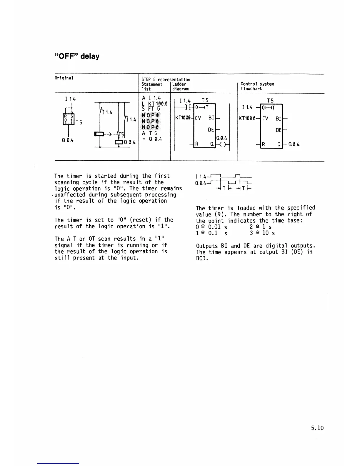
The timer is started during the first
scanning cycle
if
the result of the
logic operation is
"0". The timer remains
unaffected during subsequent processing
if
the result of the logic operation
Original
The timer is set to "0" (reset)
if
the
result of the logic operation is
"1".
The
A
T
or OT scan results in a
"l"
signal
if
the timer is running or
if
the result of the logic operation is
still present at the input.
A
I14
L
KT1000
A
T5
004
=
a
0.4
Q
0.4
STEP
5
representation
The timer is loaded with the specified
value (9). The number to the right of
the point indicates the time base:
0
=^
0.01
S
221s
l?
0.1
S
3110s
Statement
list
Outputs B1 and
DE
are digital outputs.
The time appears at output
B1 (OE) in
BCD
.
Ladder
diagram
Control system
flowchart