5.1.2
Setting /resetting operations
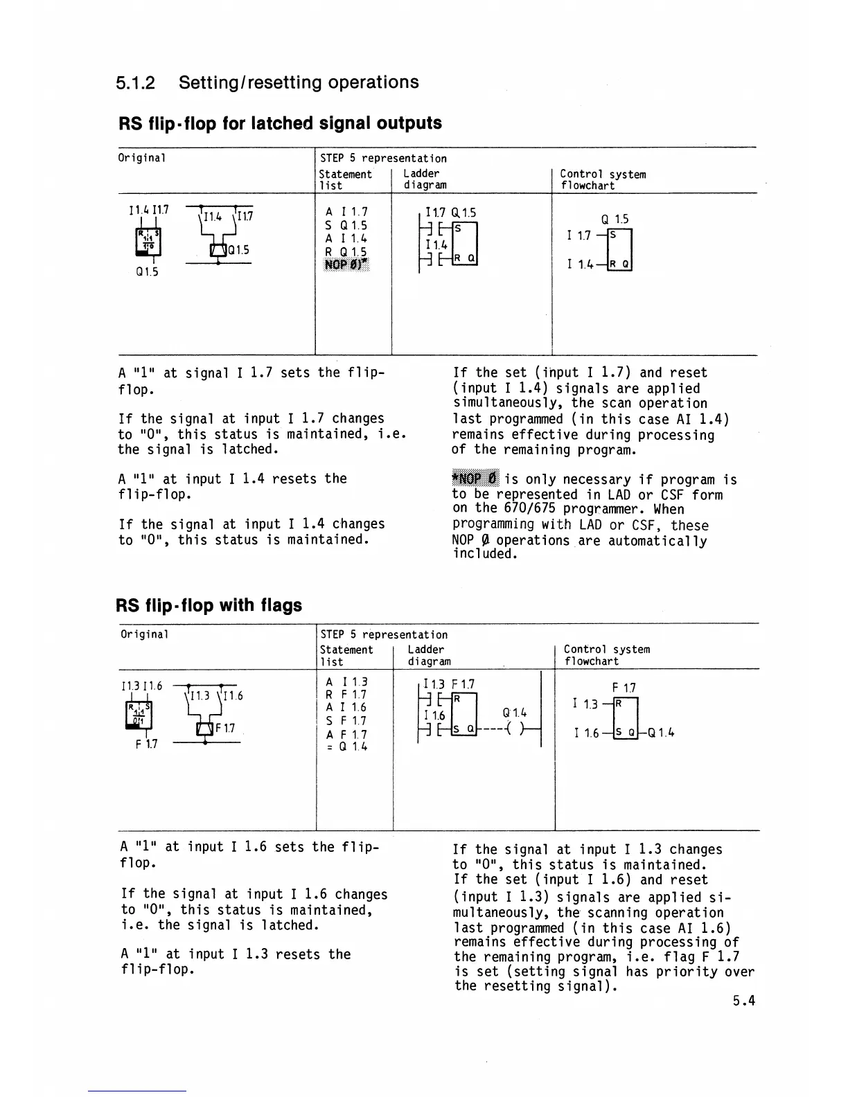
RS
flip-flop for latched signal outputs
Original
I
STEP
5
representation
:'
....
:.:':.*..::'L,::.:
....
:..
A
"1"
at input
I
1.4 resets the
@$@E;:@:
...%..:.
S..:
is only necessary
if
program is
flip-flop. to be represented in
LAD
or
CSF
form
on the
670/675 programmer. When
If
the signal at input
I
1.4 changes programming
with
LAD or
CSF,
these
to
"OU,
this status is maintained.
NOP
@
operations are automat ical
ly
i
ncl uded.
Control system
flowchart
Statement
list
11
4
I17
Q1
5
RS
flip-flop with flags
Ladder
diagram
A
I17
I
1.7
Q
1
5
S
Q15
Q
15
R
Q15
HOP
#f
R
a
Original
I
A
"1"
at signal
I
1.7 sets the flip-
If
the set (input
I
1.7) and reset
flop.
(input
I
1.4) signals are applied
simultaneously, the scan operation
If
the signal at input
I
1.7 changes
last programmed (in this case AI 1.4)
to
"ON,
this status is maintained, i.e.
remains effective during processing
the signal is latched. of the remaining program.
A
"1"
at input
I
1.6 sets the flip-
If
the signal at input
I
1.3 changes
flop.
to
"OM,
this status is maintained.
If
the set (input
I
1.6) and reset
If
the signal at input
I
1.6 changes
(input
I
1.3) signals are applied si-
to
"OM,
this status is maintained,
mu1 taneously, the scanning operation
i.e. the signal is latched.
last programmed (in this case AI 1.6)
remains effective during processing of
A
"1"
at input
I
1.3 resets the
the remaining program, i.e. flag
F
1.7
flip-flop.
is set (setting signal has priority over
the resetting signal
).
5.4
STEP
5
representation
Control system
flowchart
Statement Ladder
A
113
=
0
14
I
list
diagram