The
"Run"
and "Stop" modes
"RUN" mode
p-
In the "RUN" mode, the program is scanned
cyclically from cycle checkpoint to
cycle checkpoint. The PC is brought
into the "RUN" mode by
-
switching the mode selector to
"RUN1'
-
selecting the "PC RUN1' function of
the
programner (mode selector in "RUN"
position)
-
and on recovery of the power supply
if
the mode selector is at "RUN" and
was in the "RUN" position prior to
the power failure.
Memories
The PC has an internal program memory,
the data of which can be supported for
three years by a backup battery.
There are also two different memory
submodules (see Fig. 4).
"STOP" mode
In the "STOP" mode, the program is not
scanned and the outputs (coils) are
disabled. While the PC is in the "STOP"
state, all timers and counters and the
process 1/0 image retain the values
or states they had in the last scanning
cycle prior to the PC entering the "STOP"
state.
If
the PC is switched to "RUN",
the timers and counters (0
...
7) are
reset. The non-retentive flags and the
process 1/0 image are erased.
The
PC
is brought into the "STOP" mode
by
-
switching the mode selector to "STOP"
-
selecting the "PC STOP" function on
the programmer
-
faults or errors in program scanning,
e.g. time-out or operations that can
not be interpreted by the PC.
The cause for the PC entering the 'STOP"
state can be traced with the aid of
the "DISPLAY ESTACK" function of the
programner (see Section 4.2 of Operating
Instructions).
The memory submodules are used for pro-
gram dumping or for copying the program
should only one memory submodule be
used for a number of
PCs.
On
power-up or when the PC is switched
to
"RUN",
the contents of the memory
submodule are always copied into the
internal memory and processed there.
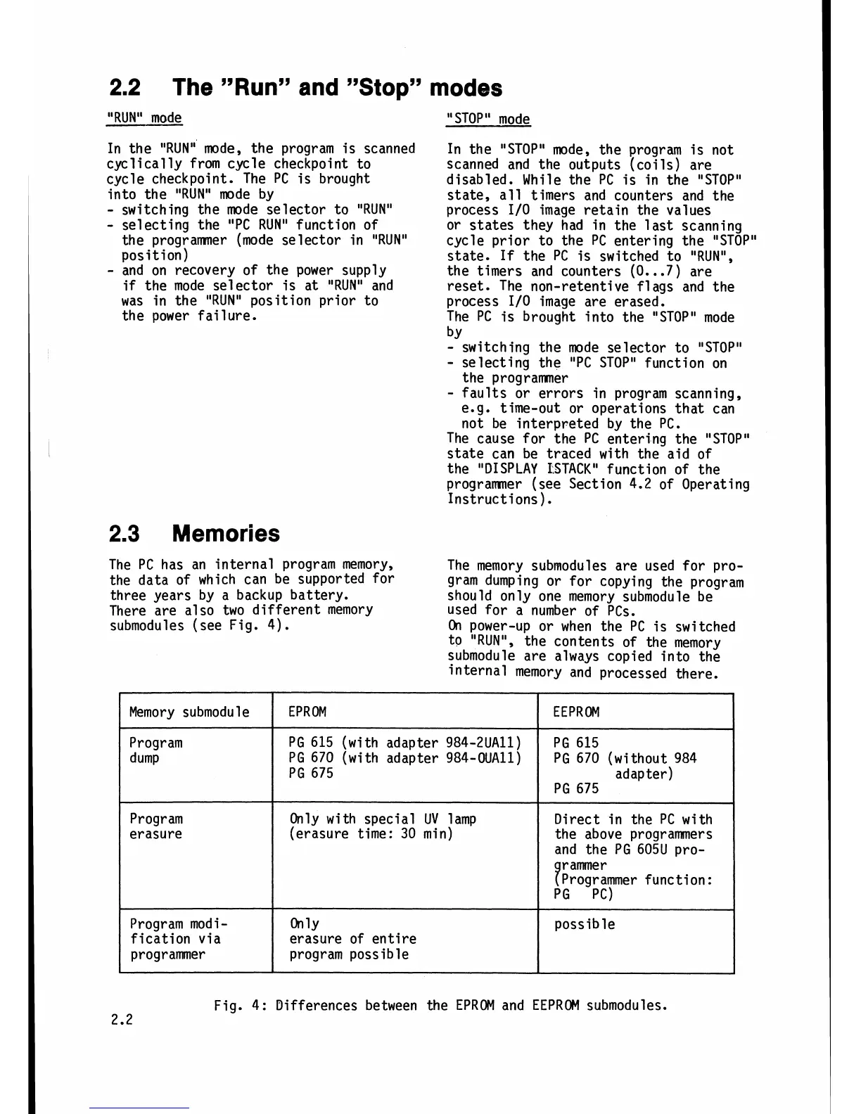
Fig. 4: Differences between the EPROM and EEPROM submodules.
Memory submodu
l
e
Program
dump
Program
erasure
Program mod
i
-
fication via
programmer
EPROM
PG
615 (with adapter 984-2UAll)
PG 670 (with adapter 984-OUAll)
PG 675
Only with special UV lamp
(erasure time: 30 min)
On
1~
erasure of entire
program possible
EEPROM
PG 615
PG 670 (without 984
adapter)
PG 675
Direct in the PC with
the above programmers
and the PG 605U
pro-
9
r
amme
r
Programmer function:
PG PC)
possible