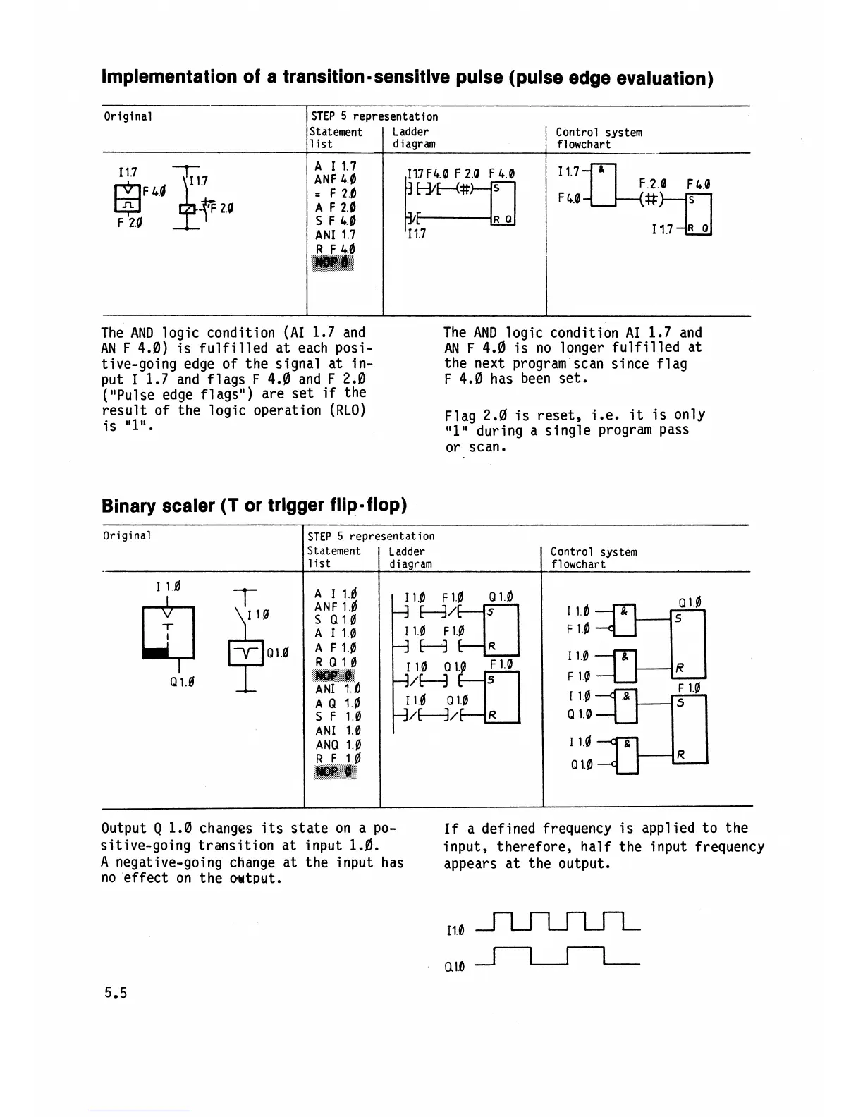
Implementation of a transition-sensitive pulse (pulse edge evaluation)
Original
l
STEP
5
representation
A
I
1.7
ANF
4.0
=
F
2.6
A
F
2.0
S
F
4.0
AN1
1.7
The AND logic condition (AI 1.7 and
The AND logic condition
AI
1.7 and
AN F 4.0) is fulfilled at each
posi-
AN
F
4.0 is no longer fulfilled at
tive-going edge of the signal at
in-
the next program scan since flag
put
I
1.7 and flags F
4.0
and F 2.0
F 4.0 has been set.
("Pulse edge flags") are set
if
the
result of the logic operation
(RLO)
Flag 2.0 is reset, i.e.
it
is only
is
"1".
"1"
during a single program pass
or scan.
Control system
flowchart
-
Statement
list
Binary scaler
(T
or trigger flip-flop)
I I
Ladder
diagram
Original
l
STEP
5
representation
A 1l.d
ANF 1.6
S
0
1.0
A
11.0
A
F1.0
R
Q
1.0
.
....:
$g$&$$$
ANI
';
I.
a
A
Q
1.0
S
F
1.0
AN1 1.0
ANQ 1.0
Output
Q
1.0 changes its state on a po-
If
a defined frequency is applied to the
sitive-going transition at input
1.fl.
input, therefore, half the input frequency
A
negative-going change at the input has
appears at the output.
no effect on the
output.
Control system
flowchart
Statement
list
Ladder
diagram