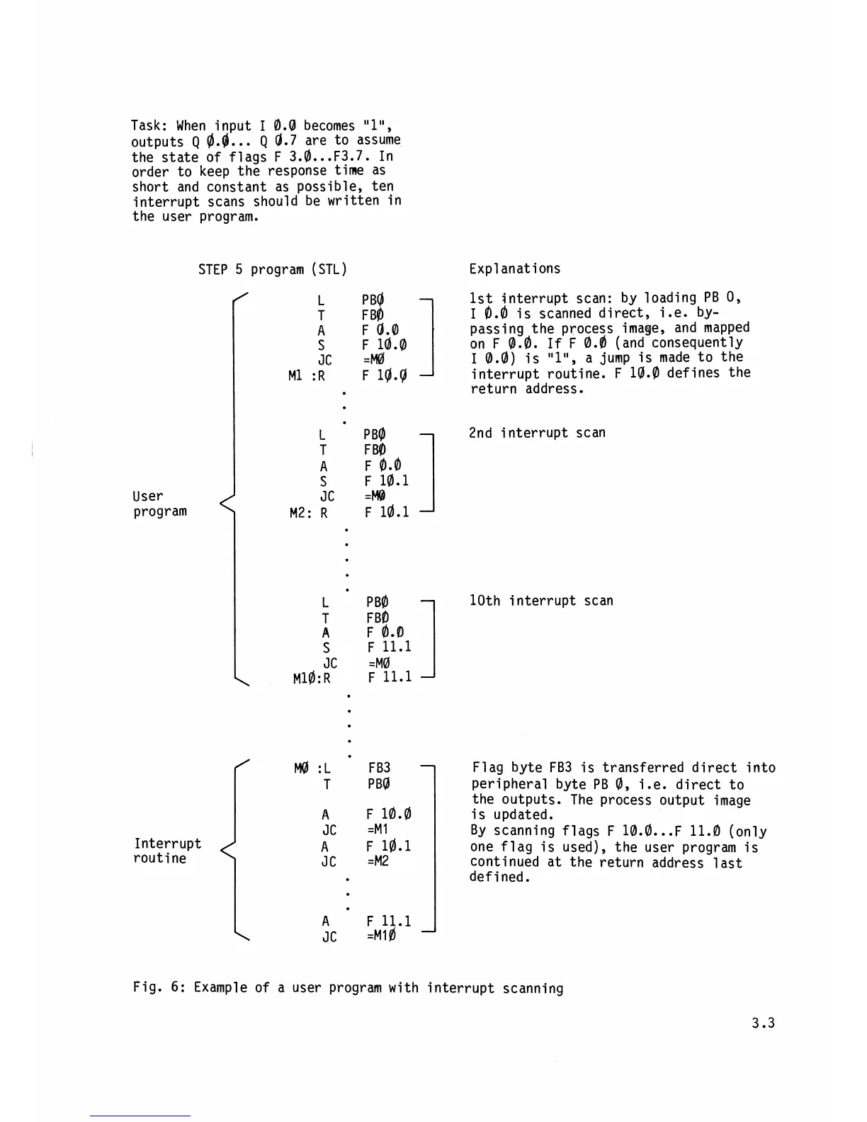
Task: When input
I
0.0
becomes
"l",
outputs
Q
@.g.
..
Q
0.7
are to assume
the state of flags F
3.a
...
F3.7. In
order to keep the response time as
short and constant as possible,
ten
interrupt scans should be written in
the user program.
User
program
STEP
5
program (STL)
Interrupt
routine
Expl
anat ions
1st interrupt scan: by loading PB
0,
I
0.0
is scanned direct, i.e. by-
passing the process image, and mapped
on F
@.a.
If
F
0.0
(and consequently
I
0.0)
is
"l",
a jump is made to the
interrupt routine.
F
10.0
defines the
return address.
2nd
i
nterrupt scan
10th interrupt scan
Flag byte FB3 is transferred direct into
peripheral byte PB
0,
i.e. direct to
the outputs. The process output image
is updated.
By scanning flags
F
10.0
...
F 11.0 (only
one flag is used), the user program is
continued at the return address last
defined.
Fig.
6:
Example of a user program with interrupt scanning