A-3
S7-200 Programmable Controller, CPU 210
C79000-G7076-C235-01
Table A-1 Technical Specifications for the S7-200 Family, continued
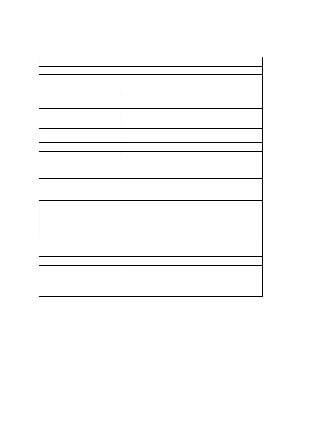
Electromagnetic Compatibility — Immunity
2
IEC 801-2 Electrostatic Discharge 8 kV air discharge to all surfaces and communication port
IEC 801-3 Radiated electromagnetic field 26 MHz to 1 GHz 10 V/m, 80% modulation with 1 kHz signal
900 MHz ± 5 MHz, 10 V/m, 50% duty cycle, 200 Hz repetition
frequency
IEC 801-4 Fast transient bursts 2 kV, 5 kHz with coupling network to AC and DC system power
2 kV, 5 kHz with coupling clamp to digital I/O and communications
IEC 801-5 Surge immunity 2 kV asymmetrical, 1 kV symmetrical
5 positive / 5 negative pulses 0°, +90°, -90° phase angle
(24 VDC circuits require external surge protection)
VDE 0160 Non-periodic overvoltage at 85 VAC line, 90° phase angle, apply 390 V peak, 1.3 ms pulse
at 180 VAC line, 90° phase angle, apply 750 V peak, 1.3 ms pulse
Electromagnetic Compatibility — Conducted and Radiated Emissions
3
EN 55011, Class A, Group 1, conducted
2
0.15 to 0.5 MHz
0.5 to 5 MHz
5 to 30 MHz
< 79 dB (µV) Quasi-peak; < 66 dB (µV) Average
< 73 dB (µV) Quasi-peak; < 60 dB (µV) Average
< 73 dB (µV) Quasi-peak; < 60 dB (µV) Average
EN 55011, Class A, Group 1, radiated
2
30 MHz to 230 kHz
230 MHz to 1 GHz
30 dB (µV/m) Quasi-peak; measured at 30 meters
37 dB (µV/m) Quasi-peak; measured at 30 meters
EN 55011, Class B, Group 1, conducted
4
0.15 to 0.5 MHz
0.5 to 5 MHz
5 to 30 MHz
< 66 dB (µV) Quasi-peak decreasing with log frequency to 56 dB (µV)
< 56 dB (µV) Average decreasing with log frequency to 46 dB (µV)
< 56 dB (µV) Quasi-peak; < 46 dB (µV) Average
< 60 dB (µV) Quasi-peak; < 50 dB (µV) Average
EN 55011, Class B, Group 1, radiated
4
30 MHz to 230 kHz
230 MHz to 1 GHz
30 dB (µV/m) Quasi-peak; measured at 10 meters
37 dB (µV/m) Quasi-peak; measured at 10 meters
High Potential Isolation Test
24 V / 5 V nominal circuits
115/230 V circuits to ground
115/230 V circuits to 115/230 V circuits
230 V circuits to 24 V / 5 V circuits
115 V circuits to 24 V / 5 V circuits
500 VAC (optical isolation boundaries)
1500 VAC
1500 VAC
1500 VAC
1500 VAC
1 Operating temperatures are based on the immediate surrounding air at the device.
2 Unit must be mounted on a grounded metallic frame with the S7-200 ground connection made directly to the mounting
metal. Cables are routed along metallic supports.
3 Applicable for all devices bearing the CE (European Community) mark.
4 Unit must be mounted in a grounded metal enclosure. AC input power line must be equipped with a Schaffner FN
680-2.5/06 filter or equivalent, 25. cm maximum wire length from filters to the S7-200. The 24 VDC supply and sensor
supply wiring must be shielded.
CPU 210 Data Sheets

 Loading...


