3-22
S7-200 Programmable Controller, CPU 210
C79000-G7076-C235-01
3.7 Creating a Status Chart
To monitor the status of selected elements in the sample program, you create a Status Chart
containing the elements you want to monitor while running the program. You can use the
Status Chart to monitor and modify the program as it runs on your PDS 210; however, you
cannot monitor the status of a program running on a CPU 210.
STEP 7-Micro/WIN provides an easy method for creating a Status Chart: simply copy any or
all of the elements in the Symbol Table and paste them into a Status Chart.
Building a Status Chart
To access the Status Chart editor, double-click the icon at the bottom of the main window.
Then enter the elements for the sample program by following these steps:
1. Select the first cell in the Address column, and type the following: Zone_1
Press ENTER to confirm your entry. This element type can only be displayed in bit format
(either 1 or 0) so you cannot change the format type.
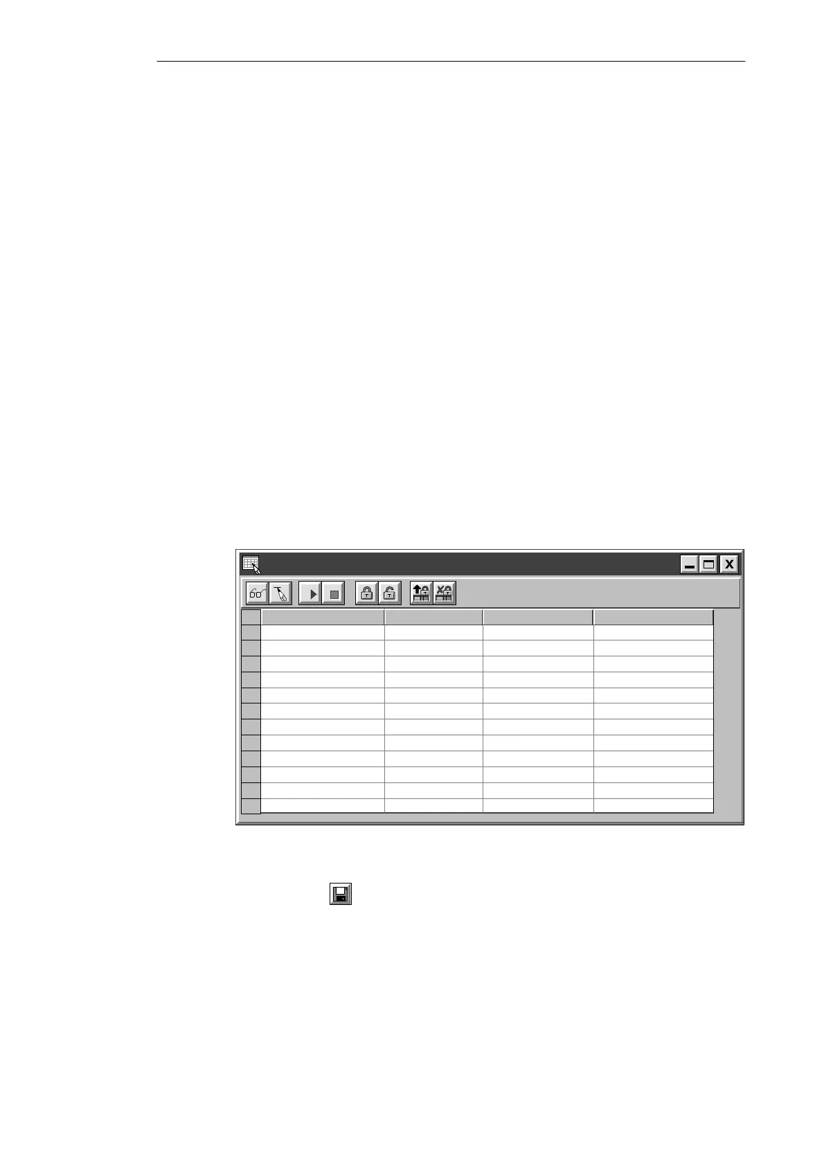
2. Select the next row, and repeat these steps for each of the remaining elements, as
shown in Figure 3-21.
You can use the menu command Edit
"
Insert Row(s) (or the INSERT or INS key) to
insert a blank row above the row containing the cursor.
Timers and counters can be displayed in other formats. With the focus in the Format column
cell, press the SPACEBAR to cycle through the formats that are valid for these element
types. For this example, select Signed for the timers.
Status Chart
Address Format Change Value ToCurrent PLC Value
Bit
Bit
Bit
Bit
Bit
“Zone_1”
Bit
Bit
Bit
Signed
2#0
2#0
2#0
2#0
“Zone_2”
“Armed”
“Panic_Alarm”
“LED”
“Alarm”
“Low_Alert”
“Modem”
“Alert_Timer”
2#0
2#0
2#0
2#0
Signed
“Exit_Timer”
Figure 3-21 Status Chart for the Sample Program
Save your Status Chart by selecting the menu command Project
"
Save All or by clicking
the Save button:
Getting Started with a Sample Program

 Loading...


