3-8
S7-200 Programmable Controller, CPU 210
C79000-G7076-C235-01
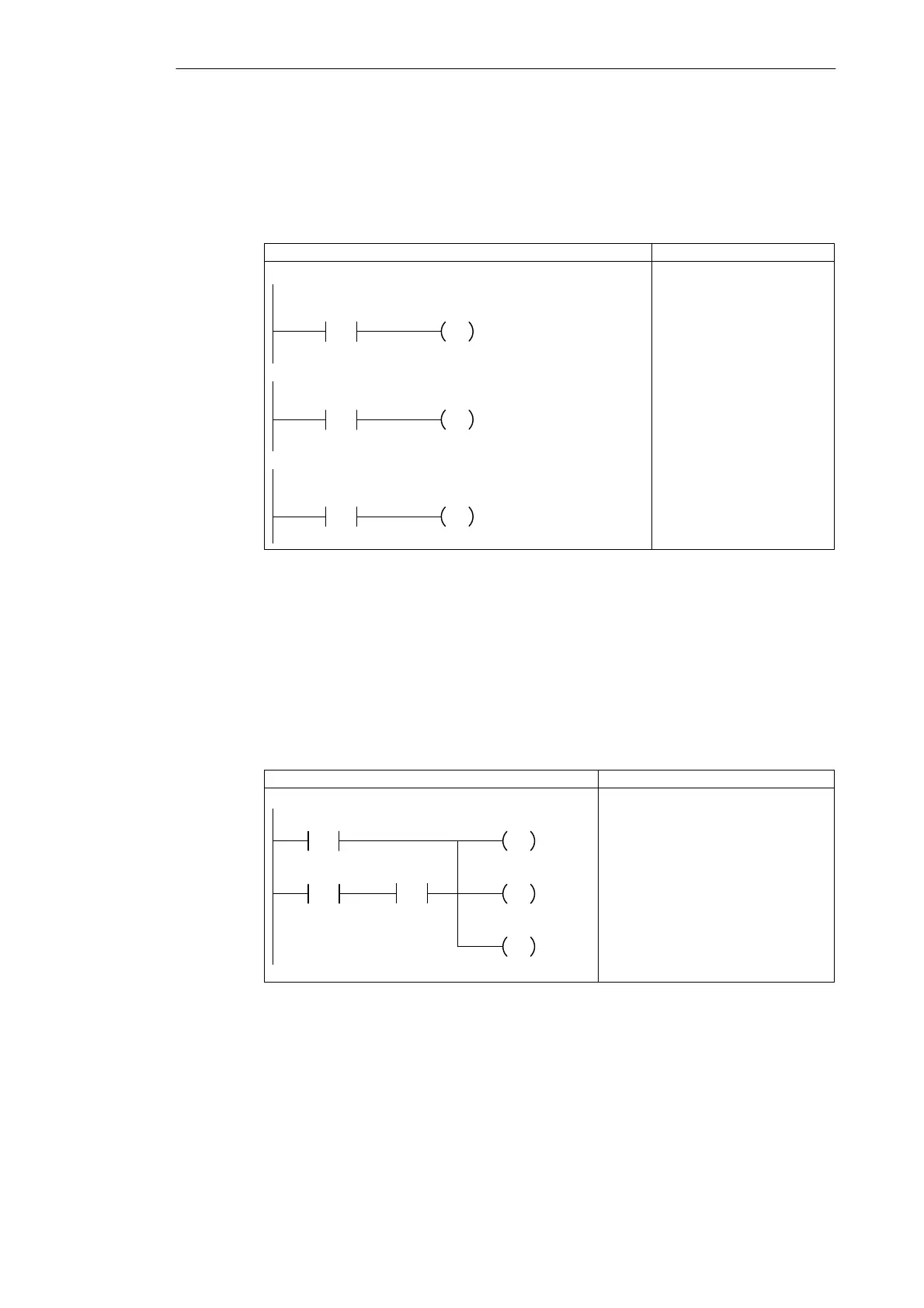
Designing the Control Logic for Turning On the Alarm and Modem Dialer
Because the outputs turn on immediately, the program uses memory bits (M) for storing the
results of the control logic. See Figure 3-9. At the end of the program, these bits turn on (or
off) the outputs.
NETWORK
LD M0.0
= Q0.0
LAD STL
LED_Bit
Network
LED
If the LED bit is on, turn on the output for the system
LED.
Alarm_Bit
Network
Alarm
Low_Bit
Network
Low_Alert
If the Alarm bit is on, turn on the output for the alarm.
If the low-level alert bit is on, turn on the output for the
low level alert.
NETWORK
LD M0.1
= Q0.1
NETWORK
LD M0.2
= Q0.2
Figure 3-9 Control Logic for Turning On the Outputs
As shown in Figure 3-10, the memory bits for the alarm siren and the modem dialer are
turned on by either of two conditions:
S Someone pushes the “panic button” (regardless of the arm/disarm state of the system
and without providing the low-level alert notification).
S The system has not been disarmed during the 60 seconds that the low-level alert
notification has been on.
Turning on the alarm also resets the low-level alert notification.
NETWORK
LD I0.3
LDW>= T0, +600
A I0.2
OLD
S M0.1, 1
S Q0.3, 1
R M0.2, 1
LAD STL
Alert_Timer
>=I
+600
Panic_Alarm
Network
Armed
Alarm_Bit
S
1
Modem
S
1
Low_Bit
R
1
Figure 3-10 Control Logic for Enabling the Alarm and Modem Bits
Getting Started with a Sample Program

 Loading...


