2-13
S7-200 Programmable Controller, CPU 210
C79000-G7076-C235-01
2.7 Using Symbolic Addressing
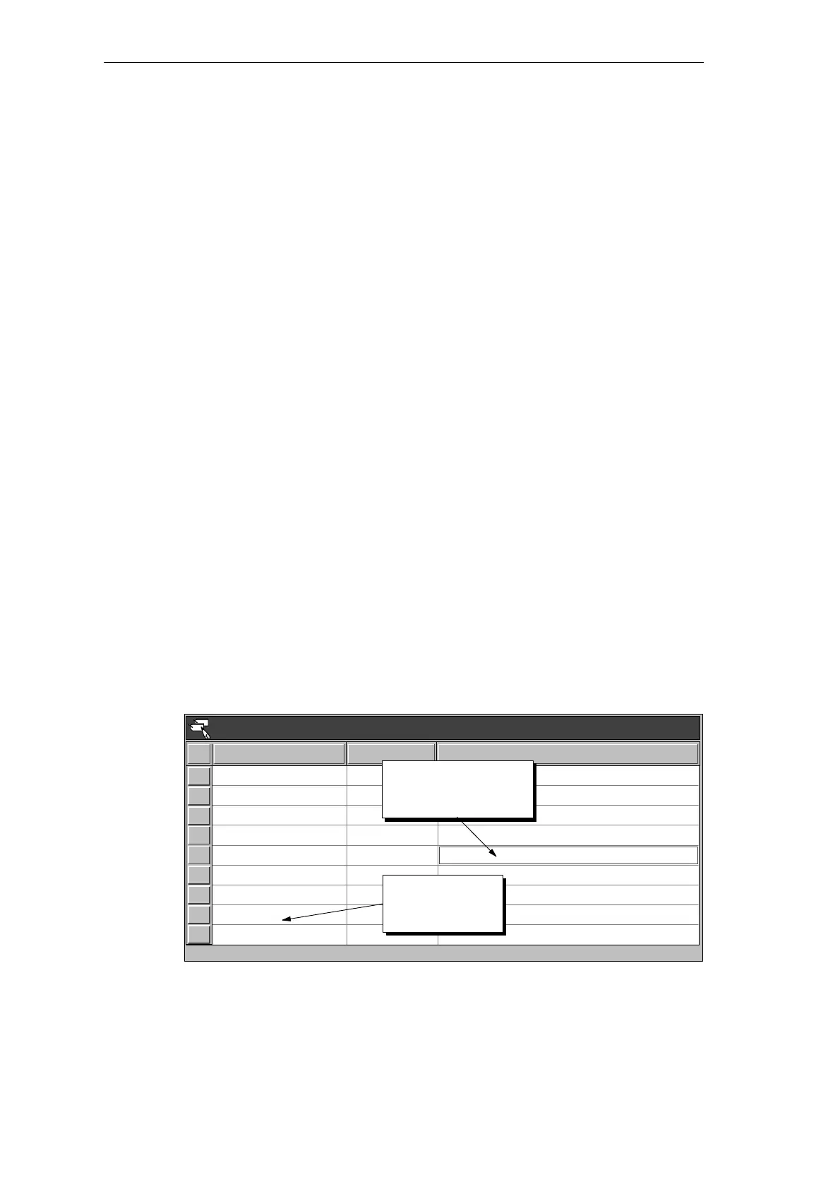
The Symbol Table allows you to give symbolic names to inputs, outputs, and internal
memory locations. See Figure 2-11. You can use the symbols you have assigned to these
addresses in the Ladder Editor, STL Editor, and Status Chart of STEP 7-Micro/WIN.
Guidelines for Entering Symbolic Addresses
The first column of the Symbol Table is used to select a row. The other columns are for the
symbol name, address, and comment. For each row, you assign a symbolic name to the
absolute address of a discrete input, output, memory location, special memory bit, or other
element. A comment for each assigned symbol is optional. Follow these guidelines when
creating a Symbol Table:
S You can enter symbol names and absolute addresses in any order.
S You can use up to 23 characters in the Symbol Name field; however, depending on the
font size of your Windows environment, you may not see the full name displayed in the
Ladder Editor.
S You can define up to 500 symbols.
S The Symbol Table is case-sensitive: for example, “Low_Alert” is considered a different
symbol from “low_alert”.
S All leading and trailing spaces will be removed from the symbol name. All adjacent
internal spaces will be converted to a single underscore. For example, if you type
“Zone 1” and press ENTER, the symbol name appears as: “Zone_1”.
S Duplicate symbol names and/or addresses will be marked by blue italics, will not be
compiled, and cannot be used in the program. Overlapping addresses are not flagged as
duplicates; for example, MW0 and MW1 overlap in memory but are not flagged as
duplicates.
Starting the Symbol Table Editor
The Symbol Table editor appears by default as a minimized window icon at the bottom of the
main window. To access the Symbol Table, double-click the icon, or click the Restore or
Maximize button on the icon (in Windows 95).
Symbol Table - untitled.sym
Zone_1
Zone_2
Armed
Panic_Alarm
LED
I0.0
I0.1
I0.2
I0.3
Q0.0
Alarm
Low_Alert
Q0.1
Q0.2
LED_Bit
M0.0
LED_Bit
M0.1
Zone 1 (switches A to F)
Enables the security system
Turns on the siren
Zone 2 (switches H to M)
Duplicate symbols
are displayed in
italics.
Symbol Name Address Comment
To clear a cell, press
delete key or spacebar
when cell is selected.
Figure 2-11 Example of a Symbol Table
Installing and Using the STEP 7-Micro/WIN Version 2.0 Software