2-3
S7-200 Programmable Controller, CPU 210
C79000-G7076-C235-01
2.2 Establishing Communication with the PDS 210
Connecting Your Computer to the PDS 210 for PPI Communications
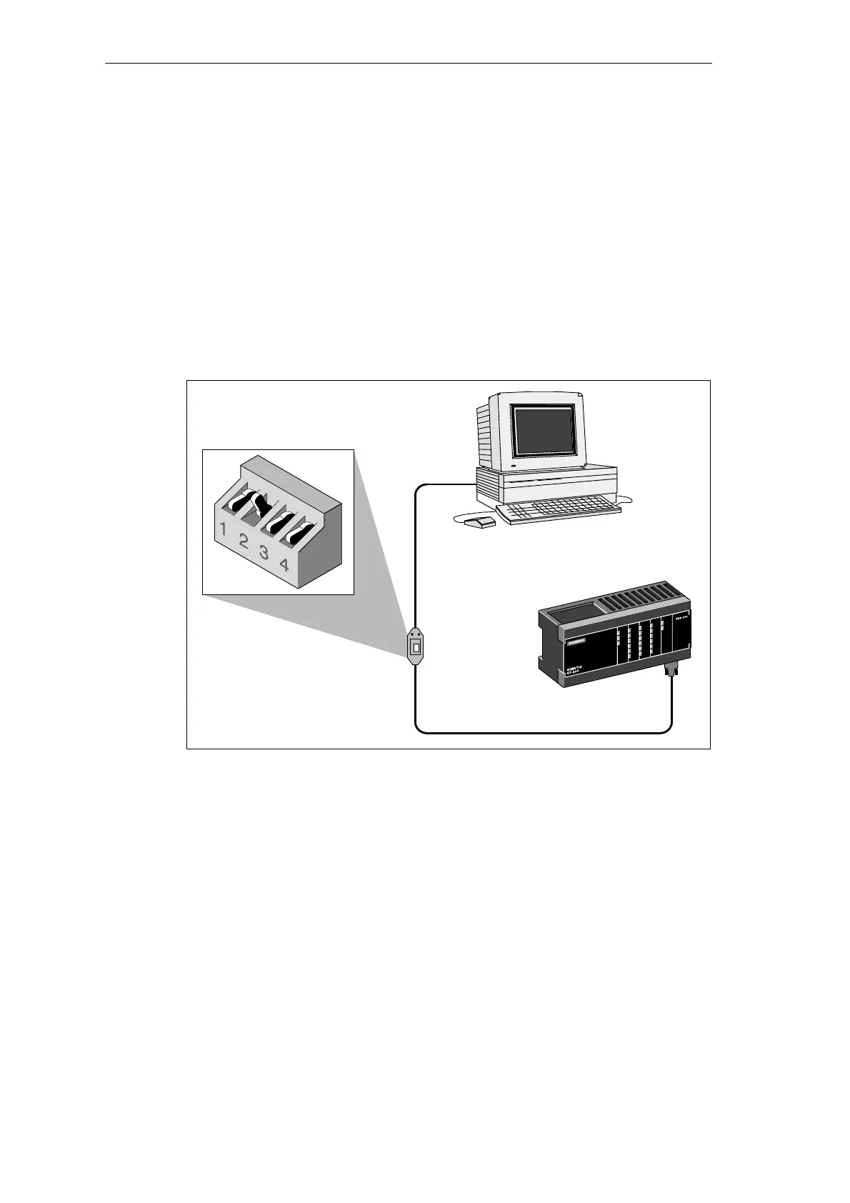
Figure 2-1 shows a typical configuration for connecting your personal computer to your
PDS 210 with the PC/PPI cable. To establish proper communications between the
components, follow these steps:
1. Set the dipswitches on the PC/PPI cable for the baud rate of 9600 baud.
2. Connect the RS-232 end of the PC/PPI cable labeled PC to the communications port of
your computer, either COM1 or COM2, and tighten the connecting screws.
3. Connect the other end (RS-485) of the PC/PPI cable to the communications port of the
PDS 210, and tighten the connecting screws.
RS-232
Program development station
(PDS 210)
PC/PPI cable
Computer
Dipswitch Settings:
0 1 0 0 = 9600 baud
RS-485
Figure 2-1 Communicating with a PDS 210 in PPI Mode
Installing and Using the STEP 7-Micro/WIN Version 2.0 Software

 Loading...


