3-24
S7-200 Programmable Controller, CPU 210
C79000-G7076-C235-01
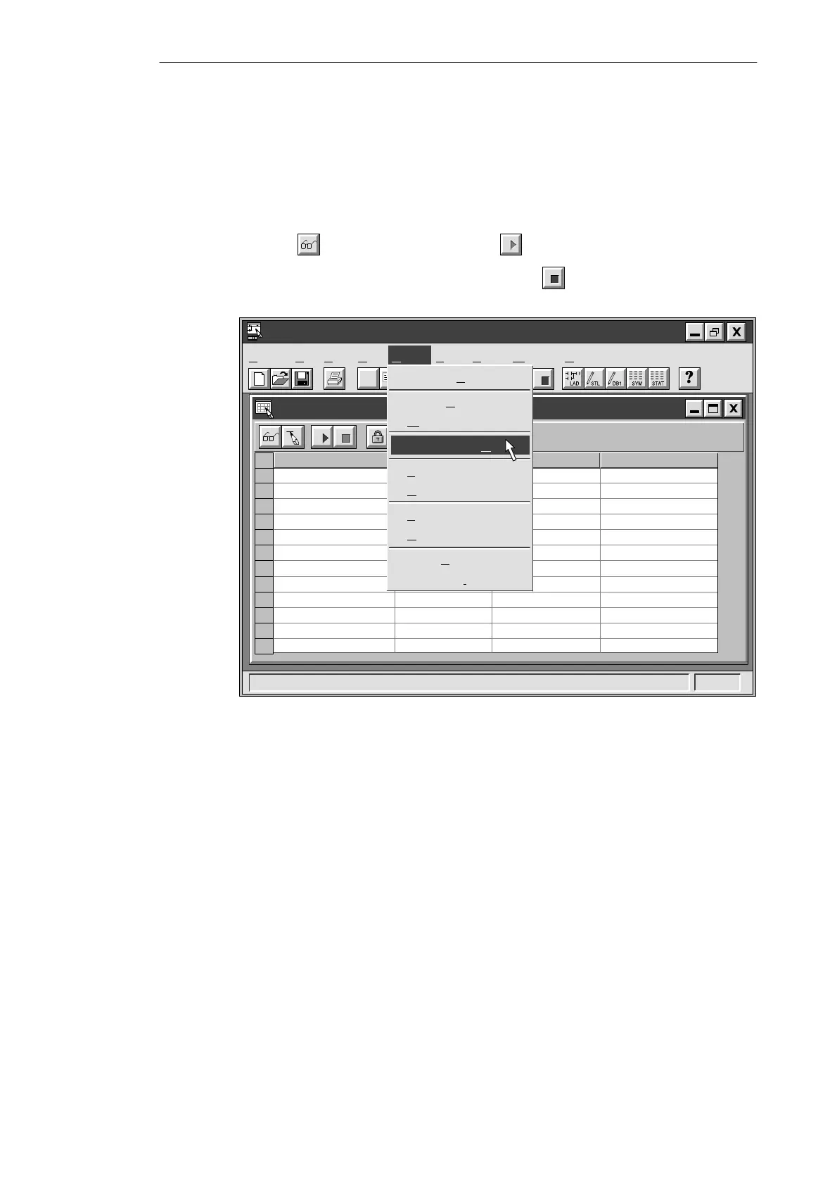
Using the Status Chart to Monitor and Modify the Current Values of the Program
You can use the Status Chart to monitor or modify the current values of any I/O points or
memory locations. Reopen the Status Chart window, if necessary, and select the menu
command Debug
"
Chart Status On, as shown in Figure 3-23. As you switch inputs on or
off with the CPU in RUN mode, the Status Chart shows the current status of each element.
S To view the current value of the elements in your program, click the Single Read
button
or the Continuous Read button in the Status Chart window.
S To stop the reading of status, click the Stop button in the Status Chart window.
✂
Project Edit View CPU Debug Tools Setup Window Help
STEP 7-Micro/WIN - c:\microwin\house.prj
Status Chart
Address Format Change Value ToCurrent PLC Value
Bit
Bit
Bit
Bit
Bit
“Zone_1”
Bit
Bit
Bit
2#0
2#0
2#0
2#0
“Zone_2”
“Armed”
“Panic_Alarm”
“LED”
“Alarm”
“Low_Alert”
“Modem”
2#0
2#0
2#0
2#0
Debug
Execute Scans...
Single R
ead
W
rite
Chart Status O
n
F
orce Value
Unforce Value
F
orce Value
Unforce Value
Read A
ll Forced
Unforce All
“Alert_Timer”
“Exit_Timer”
Figure 3-23 Monitoring the Status Chart of the Sample Program
Getting Started with a Sample Program