3-6
S7-200 Programmable Controller, CPU 210
C79000-G7076-C235-01
Designing the Control Logic for Arming and Disarming the System
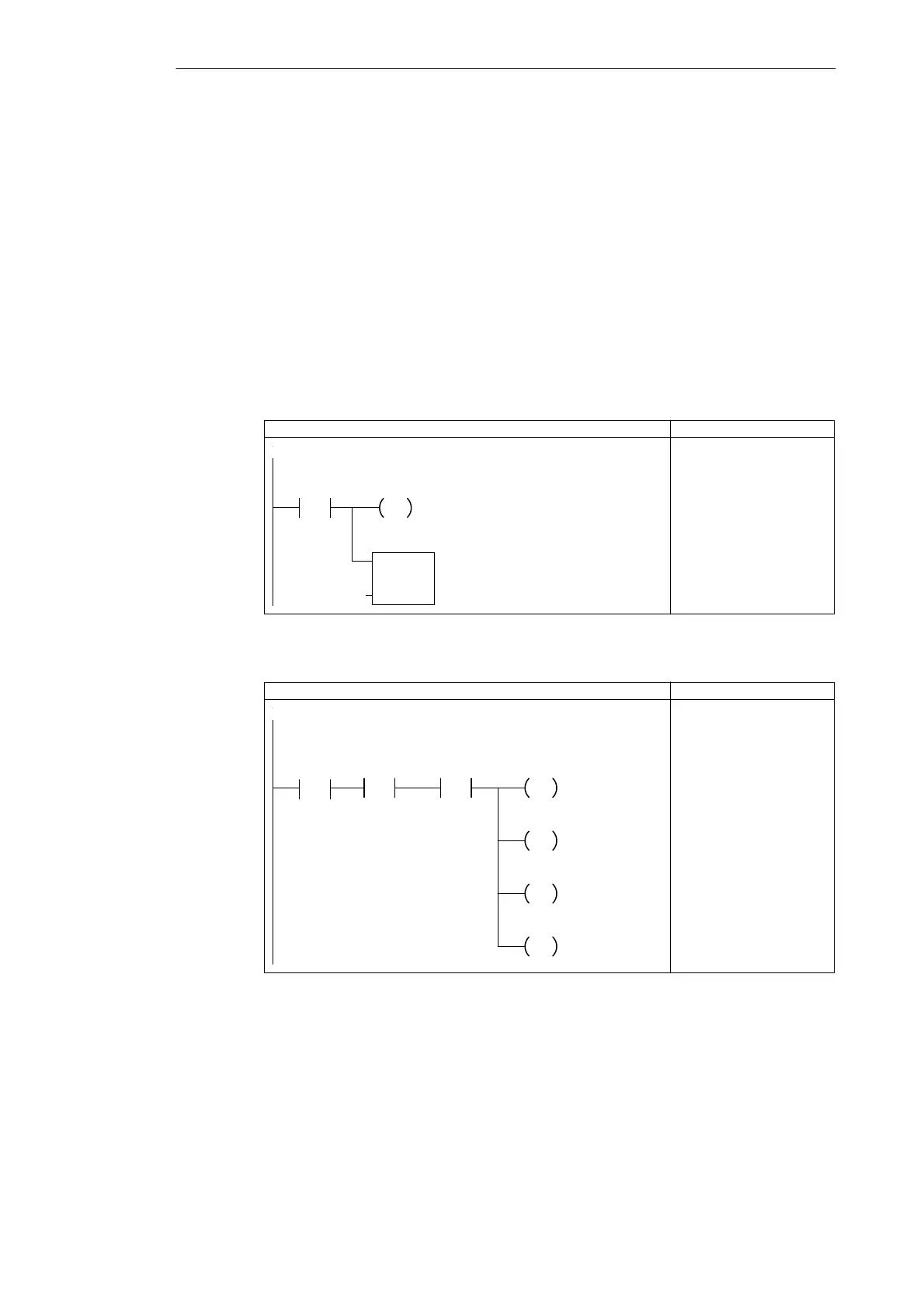
Figures 3-5 and 3-6 shows the control logic for arming and disarming the security system.
S As shown in Figure 3-5, arming the security system activates (enables) the bits of
M memory that control the outputs (alarm siren and modem dialer). The control logic for
arming the system also provides a delay between the turning on of the arm/disarm switch
and the activation of the security system. This allows time for the owner to arm the
system and exit the house. (There is a different timer that controls a low-level alert
notification that allows the owner to disarm the system.)
S As shown in Figure 3-6, disarming the security system stops the notification and alarm
sequence.
Before the security system has been armed, the LED flashes on and off if one of the zones is
open. Figure 3-7 shows the control logic for using one of the SM bits (SM0.5) to generate the
on/off pulse for the LED.
LAD STL
Network
Armed
NETWORK
LD I0.2
S M0.0, 1
TON T2, +0
If the system is armed, then set the lamp bit and start the
exit timer.
LED_Bit
S
1
TON
IN
PT
Exit_Timer
+0
Figure 3-5 Control Logic for Arming the Security System
LAD STL
Network
Panic_Alarm
/
LED_Bit
R
1
Armed
/
Alarm_Bit
R
1
Low_Bit
R
1
Modem
R
1
NETWORK
LDN I0.2
EU
AN I0.3
R M0.0, 1
R M0.1, 1
R M0.2, 1
R Q0.3, 1
If the system is not armed, and the panic alarm is not on,
then reset the lamp bit, the alarm bit, the low-level alert bit,
and the modem bit.
P
Figure 3-6 Control Logic for Disarming the Security System
Getting Started with a Sample Program