3-7
S7-200 Programmable Controller, CPU 210
C79000-G7076-C235-01
NETWORK
LDN I0.2
LDN I0.0
ON I0.1
ALD
A SM0.5
ED
S M0.0, 1
Network
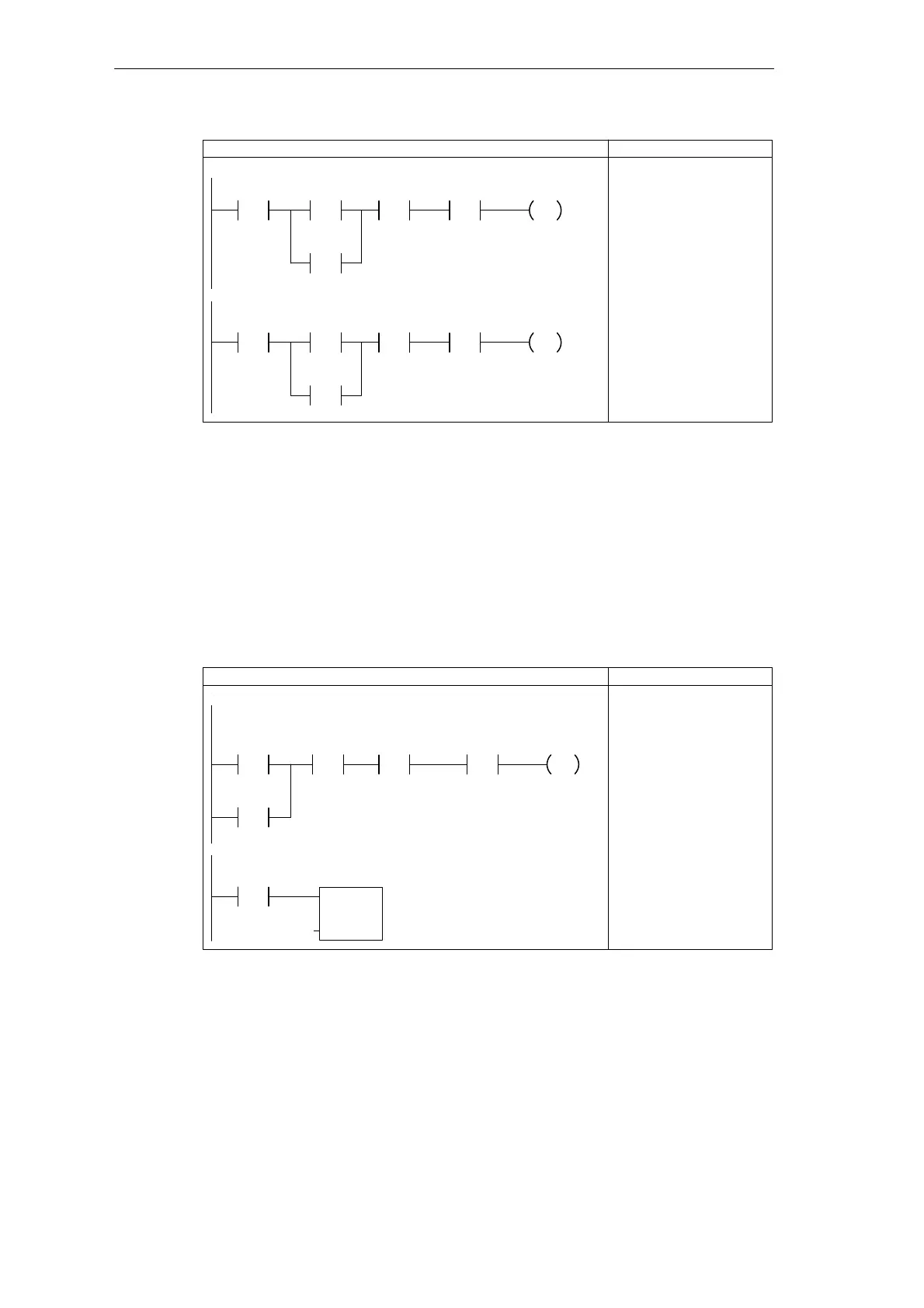
LAD STL
Network
Zone_1
/
LED_Bit
S
1
Armed
/
Zone_2
/
SM0.5
Use the negative transition of SM0.5 to turn the LED on.
Use the positive transition of SM0.5 to turn the LED off.
N
Zone_1
/
LED_Bit
R
1
Armed
/
Zone_2
/
SM0.5
P
NETWORK
LDN I0.2
LDN I0.0
ON I0.1
ALD
A SM0.5
EU
R M0.0, 1
Figure 3-7 Control Logic for Flashing the LED On and Off
Designing the Control Logic for Turning On the Low-Level Alert Notification
On a breach of security (created when either Zone 1 or Zone 2 opens after the security
system has been armed), the program turns on the low-level alert notification. This allows the
owner a specified time to disarm the system (such as when when re-entering the house). As
shown in Figure 3-8, the program monitors the states of both zones and the arm/disarm
switch. It also allows for the exit time (90 seconds).
After a breach of security has been identified, the program starts the timer for the low-level
alert notification.
NETWORK
LDN I0.0
ON I0.1
A I0.2
AN M0.1
LDW>= T2, +900
= M0.2
Network
LAD STL
Network
Armed
Low_Bit
Zone_1
/
Zone_2
/
Alarm_bit
/
TON
IN
PT
Alert_Timer
+0
Low_Bit
NETWORK
LD M0.2
TON T0, +0
If the system is armed and the alarm is not already on, then
turn on the low-level alert bit when either Zone 1 or Zone 2
opens.
If the low-level alarm bit is set (on), then start the Alert
timer.
Exit_Timer
>=I
+900
Figure 3-8 Control Logic for Turning On the Low-Level Alert Notification
Getting Started with a Sample Program