A-11
S7-200 Programmable Controller, CPU 210
C79000-G7076-C235-01
3.3K ohms
470 ohms
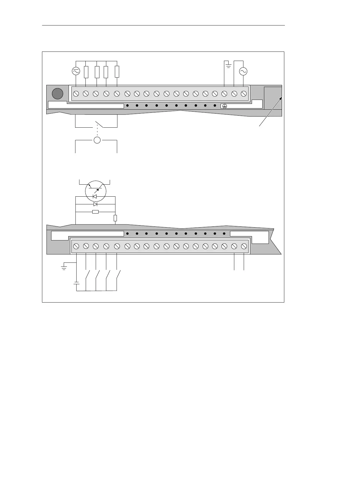
Note:
1. Actual component values may vary.
2. For AC outputs, connect AC line to the L terminal.
N L1 85–264
VAC
Outputs (30 VDC / 250 VAC)
N (-)
L (+)
Power Supply
1L 0.0 0.1 0.2 0.3
RELAY
OUTPUTS
ML+
DC
SENSOR
SUPPLY
Inputs (15 to 30 VDC)
24 VDC Power for Input Sensors
+
1M 0.0 0.1 0.2 0.3
DC 24V
INPUTS
Location of the Analog
Adjustment Potentiometer
and the Memory Cartridge
Figure A-4 Connector Terminal Identification for PDS 210 AC/DC/Relay
CPU 210 Data Sheets

 Loading...


