1-11
S7-200 Programmable Controller, CPU 210
C79000-G7076-C235-01
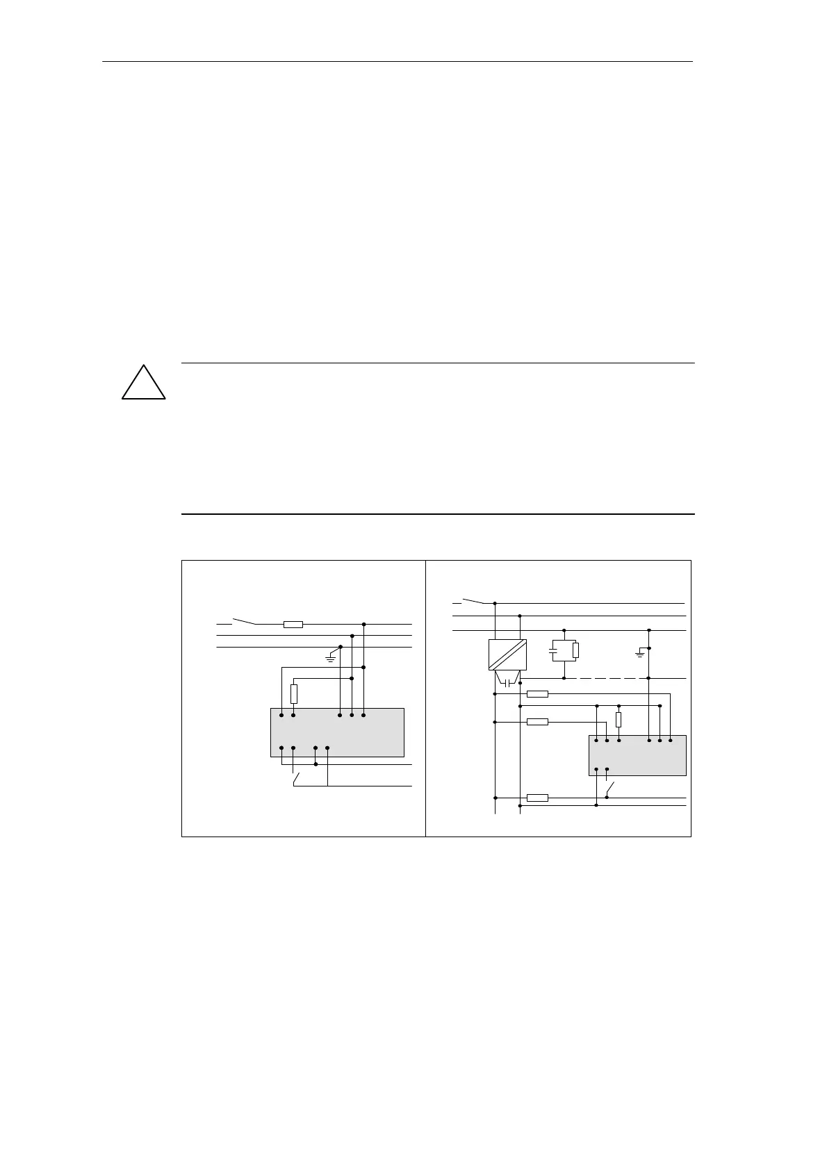
S Install or equip ungrounded DC power supplies with a resistor and a capacitor in parallel
(6) from the power source common to protective earth ground. The resistor provides a
leakage path to prevent static charge accumulations, and the capacitor provides a drain
for high frequency noise. Typical values are 1M Ω and 4700 pf. You can also create a
grounded DC system by connecting the DC power supply to ground (7).
S Connect all CPU 210 ground terminals to the closest available earth ground (8) to
provide the highest level of noise immunity. It is recommended that all ground terminals
be connected to a single electrical point. Use 14 AWG or 1.5 mm
2
wire for this
connection.
S Always supply 24 VDC circuits from a source that provides safe electrical separation from
120/230 VAC power and similar hazards. Refer to the following documents for standard
definitions of “safe separation”: PELV (protected extra low voltage) according to
EN60204-1, and Class 2 or Limited Voltage/Current Circuit according to UL 508.
Warning
Connecting an external 24 VDC power supply in parallel with the DC sensor supply of the
CPU 210 can result in a conflict between the two supplies as each seeks to establish its
own preferred output voltage level. The result of this conflict can be shortened lifetime or
immediate failure of one or both power supplies, with consequent unpredictable operation
of the PLC system. Unpredictable operation could result in death or serious injury to
personnel, and/or damage to equipment and property.
The CPU 210 DC Sensor Supply and any external power supply should provide power to
different points, with at most one connection between the two supplies.
L1
N
PE
(1)
DO
DI
P/S
CPU 210
DC/DC/DC
(5)
(6)
(2)
(3)
(4)
(7)
L+ M
24 VDC
AC
DC
(8)
Floating (6) or Grounded (7)
L1
N
PE
(A)
(D)
DO
DI
P/S
M L+
(C)
CPU 210
AC/DC/Rly
(E)
Fuse
(B)
(B)
120/230 VAC Using a Single Overcurrent
Switch to Protect the CPU and Load Wiring
Isolated DC System Installation
Figure 1-11 Wiring Guidelines for AC and DC Installation
Installing the S7-200 CPU 210
!

 Loading...


