3-27
S7-200 Programmable Controller, CPU 210
C79000-G7076-C235-01
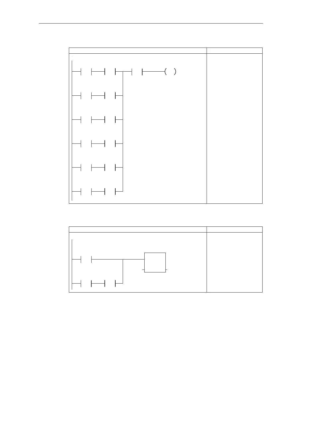
Network 11
LAD STL
NETWORK
LDW= MW1, +1
A M4.0
LDW= MW1, +2
A M4.1
LDW= MW1, +3
A M4.2
LDW= MW1, +6
A M4.5
LDW= MW1, +7
A M4.6
LDW= MW1, +8
A M4.7
OLD
AN I0.2
S M0.0, 1
If the step counter equals a particular
value and the corresponding bit pattern
is on, set the LED bit if the system is
not armed.
M4.0 I0.2
/
M0.0
S
1
MW1
==I
+1
M4.1MW1
==I
+2
M4.2MW1
==I
+3
M4.5MW1
==I
+6
M4.6MW1
==I
+7
M4.7MW1
==I
+8
Figure 3-27 Control Logic for Controlling the Blink Pattern
LAD STL
Network 12
NETWORK
LDW>= MW1, +10
LD I0.0
A I0.1
OLD
MOVW +0, MW1
If the step counter equals 10 and both Zone 1 and
Zone 2 are closed, then reset the step counter to 0.
MW1
>=I
+10
MOV_W
EN
IN OUT+0 MW1
I0.0
I0.1
Figure 3-28 Control Logic for Resetting the Counter
Getting Started with a Sample Program

 Loading...


