Operating and display elements
2.1 Operating and display elements: CPU 31xC
CPU 31xC and CPU 31x, Technical data
Manual, Edition 08/2004, A5E00105475-05
2-3
Mode selector switch
Use the mode selector switch to set the CPU operating mode.
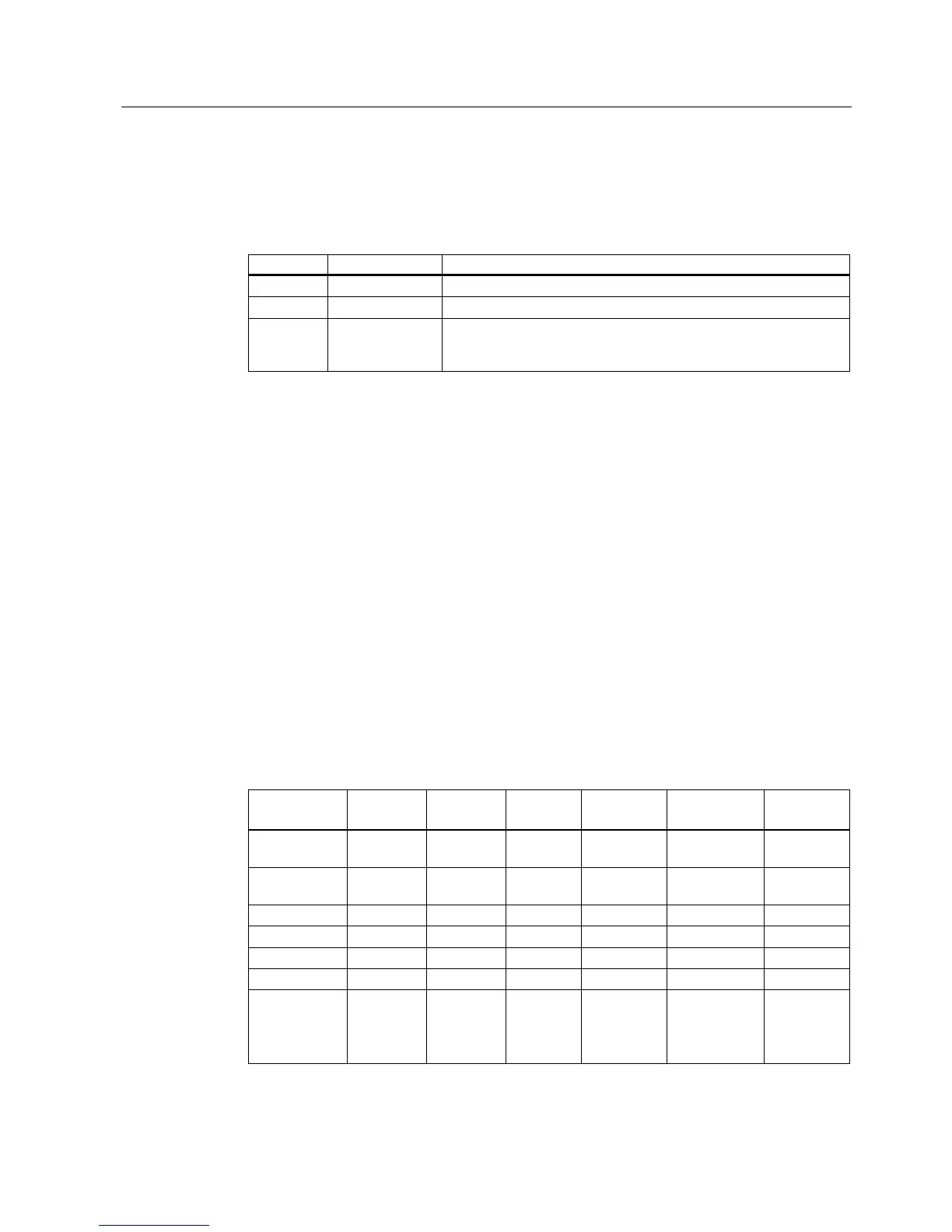
Table 2-1 Positions of the mode selector switch
Position Meaning Description
RUN RUN mode The CPU executes the user program.
STOP STOP mode The CPU does not execute a user program.
MRES CPU memory
reset
Mode selector switch position with pushbutton function for CPU
memory reset. A CPU memory reset by means of mode selector
switch requires a specific sequence of operation.
Reference
• CPU operating modes:
STEP 7 Online Help
.
• Information on CPU memory reset:
Operating instructions CPU 31xC and CPU31x,
Commissioning, Commissioning Modules, CPU Memory Reset by means of Mode
Selector Switch
• Evaluation of the LEDs upon error or diagnostic event:
Operating Instructions CPU 31xC
and CPU 31x, Test Functions, Diagnostics and Troubleshooting, Diagnostics with the
help of Status and Error LEDs
Power supply connection
Each CPU is equipped with a double-pole power supply socket. The connector with screw
terminals is inserted into this socket when the CPU is delivered.
Differences between the CPUs
Table 2-2 Differences of the CPUs 31xC
Element CPU
312C
CPU
313C
CPU
313C-2 DP
CPU
313C-2 PtP
CPU
314C-2 DP
CPU
314C-2 PtP
9-pole DP
interface (X2)
– – X – X –
15-pole PtP
interface (X2)
– – – X – X
Digital inputs 10 24 16 16 24 24
Digital outputs 6 16 16 16 16 16
Analog inputs – 4 + 1 – – 4 + 1 4 + 1
Analog outputs – 2 – – 2 2
Technological
functions
2 counters 3 counters 3 counters 3 counters 4 counters
1 channel for
positioning
4 counters
1 channel
for
positioning

 Loading...


