Operating and display elements
2.2 Operating and display elements: CPU 31x
CPU 31xC and CPU 31x, Technical data
Manual, Edition 08/2004, A5E00105475-05
2-11
2.2.4 Status and error displays of the CPU 31x
General status and error displays
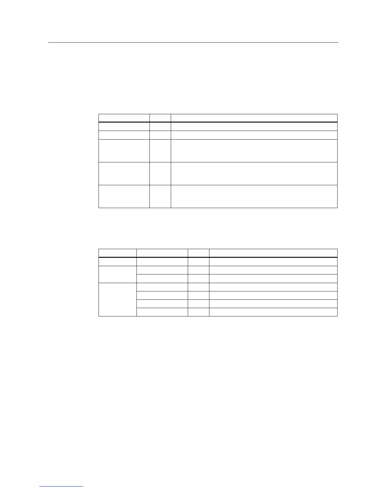
Table 2-6 General status and error displays of the CPU 31x
LED designation Color Meaning
SF red Hardware or software error.
DC5V green 5-V power for the CPU and the S7-300 bus
FRCE yellow LED is lit: Active force job
LED flashes at 2 Hz: Node flash test function (only CPUs with
firmware V2.2.0 or higher)
RUN green CPU in RUN
The LED flashes during STARTUP at a rate of 2 Hz, and in HOLD
state at 0.5 Hz.
STOP yellow CPU in STOP, or HOLD, or STARTUP
The LED flashes at 0.5 Hz when the CPU requests a memory reset,
and during the reset at 2 Hz.
Displays for the X1 and X2 interfaces
Table 2-7 Bus error displays of CPU 31x
CPU LED designation Color Meaning
315-2 DP BF red Bus error at DP interface (X2)
BF1 red Bus error at interface 1 (X1) 317-2 DP
BF2 red Bus error at interface 2 (X1)
BF1 red Bus error at interface 1 (X1)
BF2 red Bus error at interface 2 (X1)
LINK green Active communication at interface 2 (X2).
31x-2 PN/DP
RX/TX yellow Receive / Transmit data at interface 2 (X2)
Reference
• CPU operating modes:
STEP 7 Online Help
.
• Information on CPU memory reset:
Operating instructions CPU 31xC and CPU31x,
Commissioning, Commissioning Modules, CP Memory Reset by means of Mode Selector
Switch
• Evaluation of the LEDs upon error or diagnostic event:
Operating Instructions CPU 31xC
and CPU 31x, Test Functions, Diagnostics and Troubleshooting, Diagnostics with the
help of Status and Error LEDs

 Loading...


