Testing functions, Diagnostics and Fault Elimination
S7-300 Programmable Controller Hardware and Installation
10-22 A5E00105492-01
10.6.4 Structure of slave diagnostic data
Structure of slave diagnostic data
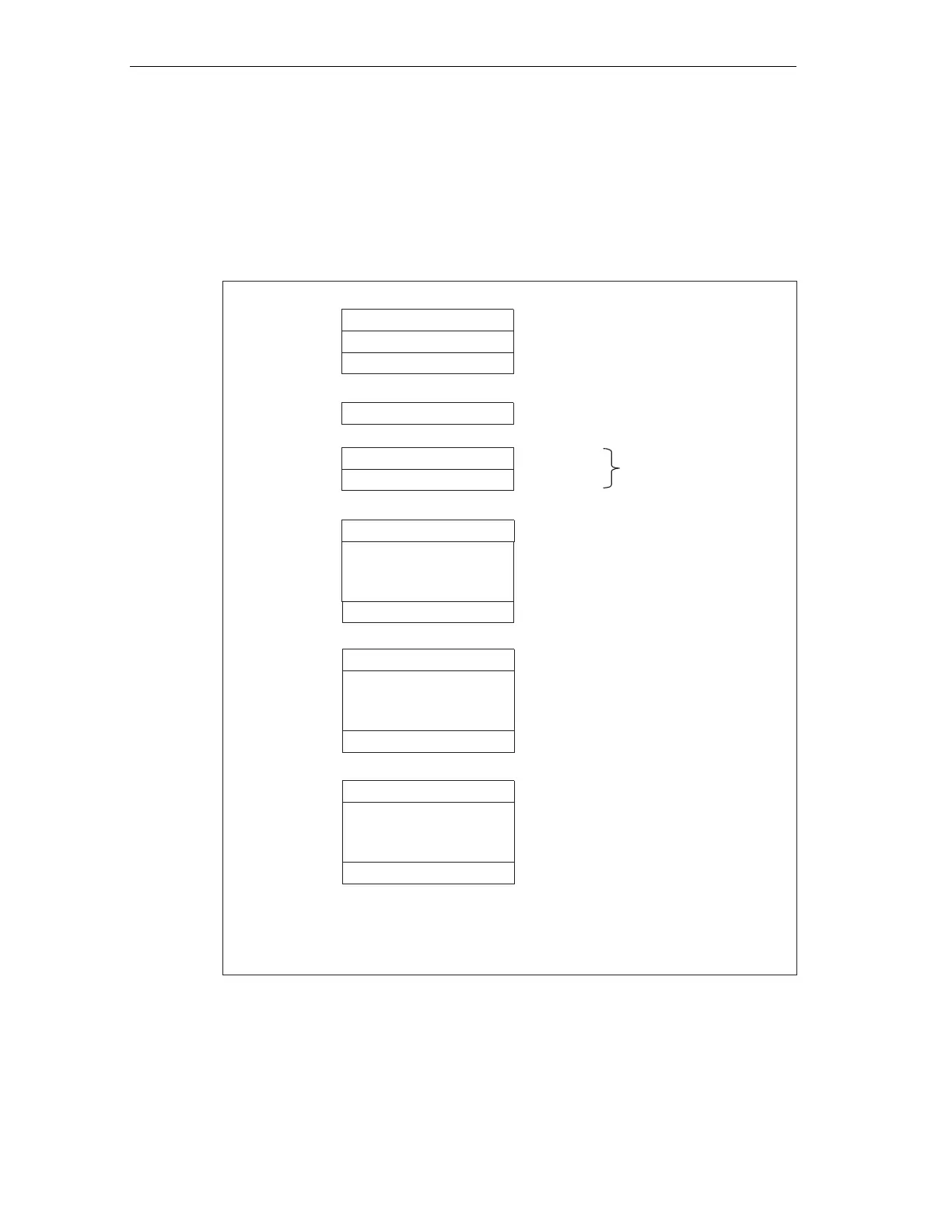
The figure below shows the structure of the diagnostics message frame for slave
diagnostics.
Station status 1 to 3
Byte 0
Byte 1
Byte 2
Byte 3
Master PROFIBUS address
Byte 4
Byte 5
Low-Byte
High-Byte
Manufacturer ID
Byte 6
to
Module diagnostics
Byte x-1
.
.
.
length depends on the number of
the configured areas of the
Intermediate memory)
1
1
Exception: if the is wrongly configured,DP master
the DP slave will interprete 35 configured address areas
(46 in byte 6)
.
.
.
Modul status (device-specific diagnostics)
Byte x+1
to
Byte y-1
length depends on the number
of the configured address areas)
.
.
.
Interrupt status (device-specific diagnostics)
Byte y
to
Byte z
(length depends on
interrupt type)
H
Figure 10-7 Structure of slave diagnostic data

 Loading...


